
Dynamic traffic light

a technology of dynamic traffic light and brake light, which is applied in the direction of optical signalling, signalling/lighting devices, transportation and packaging, etc., can solve the problems of insufficient information in the brake lighting system currently used in vehicles, the primitive and static brake lighting system presently used on vehicles, and the significant consequences of speed reduction

Inactive Publication Date: 2001-04-03
KASHEFY HAMID R
View PDF17 Cites 18 Cited by
  • Summary
  • Abstract
  • Description
  • Claims
  • Application Information

AI Technical Summary

Problems solved by technology

Dynamic Traffic Light takes the place of centre high mounted stop lamps on motor vehicles, since the brake lighting system presently used on vehicles is too primitive and too static.
In many cases this decrease in speed has significant consequences but it is not informed to following drivers by any light.
Therefore, the brake lighting system currently used in vehicles is not informative enough to following drivers and it is not sufficiently appropriate for a goal so important as to prevent traffic crashes.
The result is false flashes of green light since these flashes are supposed to reflect increase in speed of car.
Accidents occur when speed variations happen.
One trivial but inconvenient way of transmission of the mentioned pulses is to extend a wire from transmitter (which is installed near the speedometer) to the receiver in the rear of vehicle.

Method used


Image

  • Dynamic traffic light
  • Dynamic traffic light
  • Dynamic traffic light

Examples


Embodiment Construction

If differential ratio of a car is 3.5 to 1, then r should be: r=(10.44*3.5) / 2=18.27" Therefore, for a car with differential ratio of 3.5, wheel of size 18.27" will result in one flash per exactly every 3.0 km / h increase or decrease in speed, if dip switch is set to 2. So we can maintain an standard unit of speed for flashing a lamp of Dynamic Traffic Light and for displaying speed levels. Similarly the differential ratio can be adjusted in accordance with a selected value for the wheel size and for variable n. Alternatively, variable P can be adjusted based on a fixed value for the differential ratio (d), wheel size (r) and variable n.


PUM


Abstract

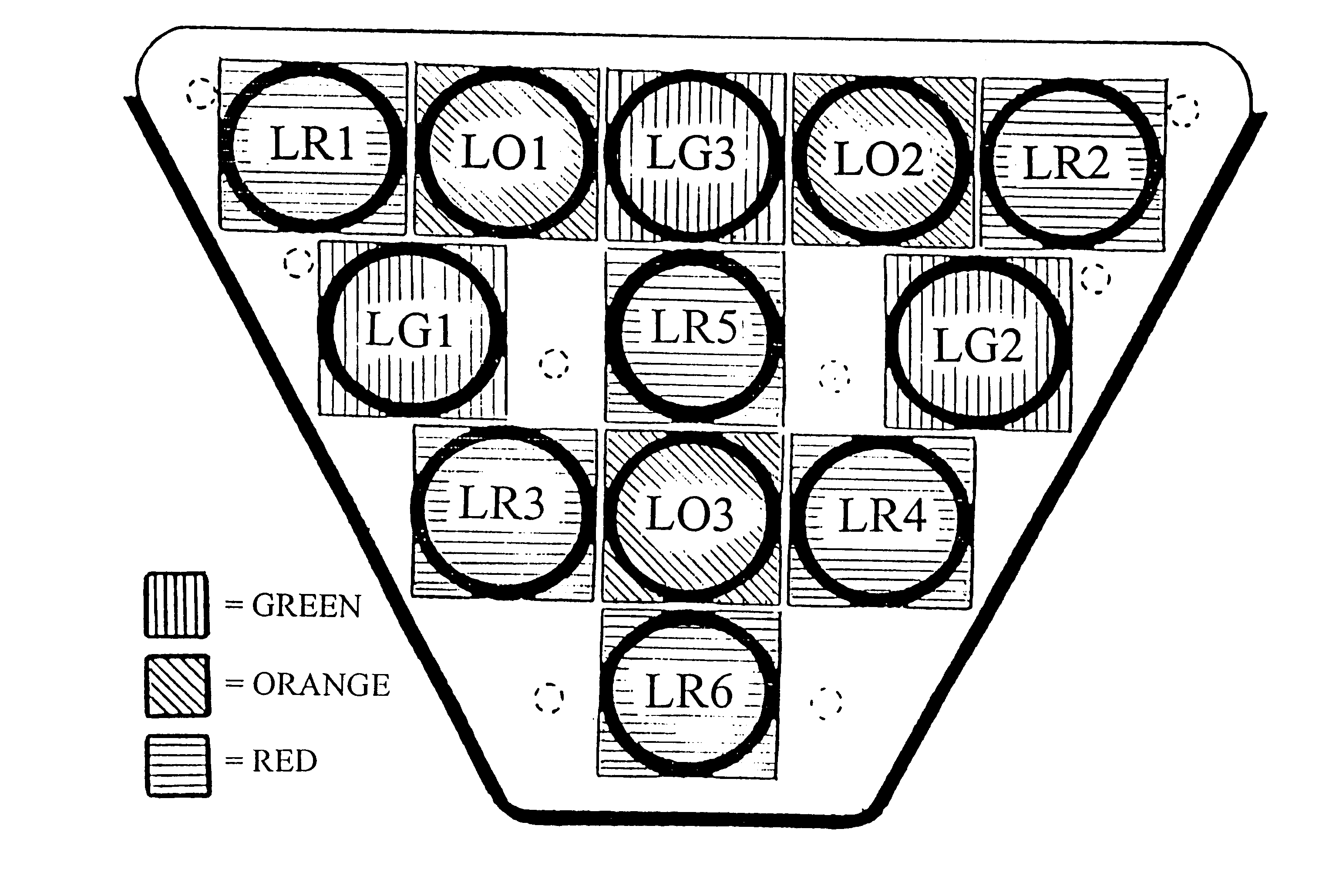
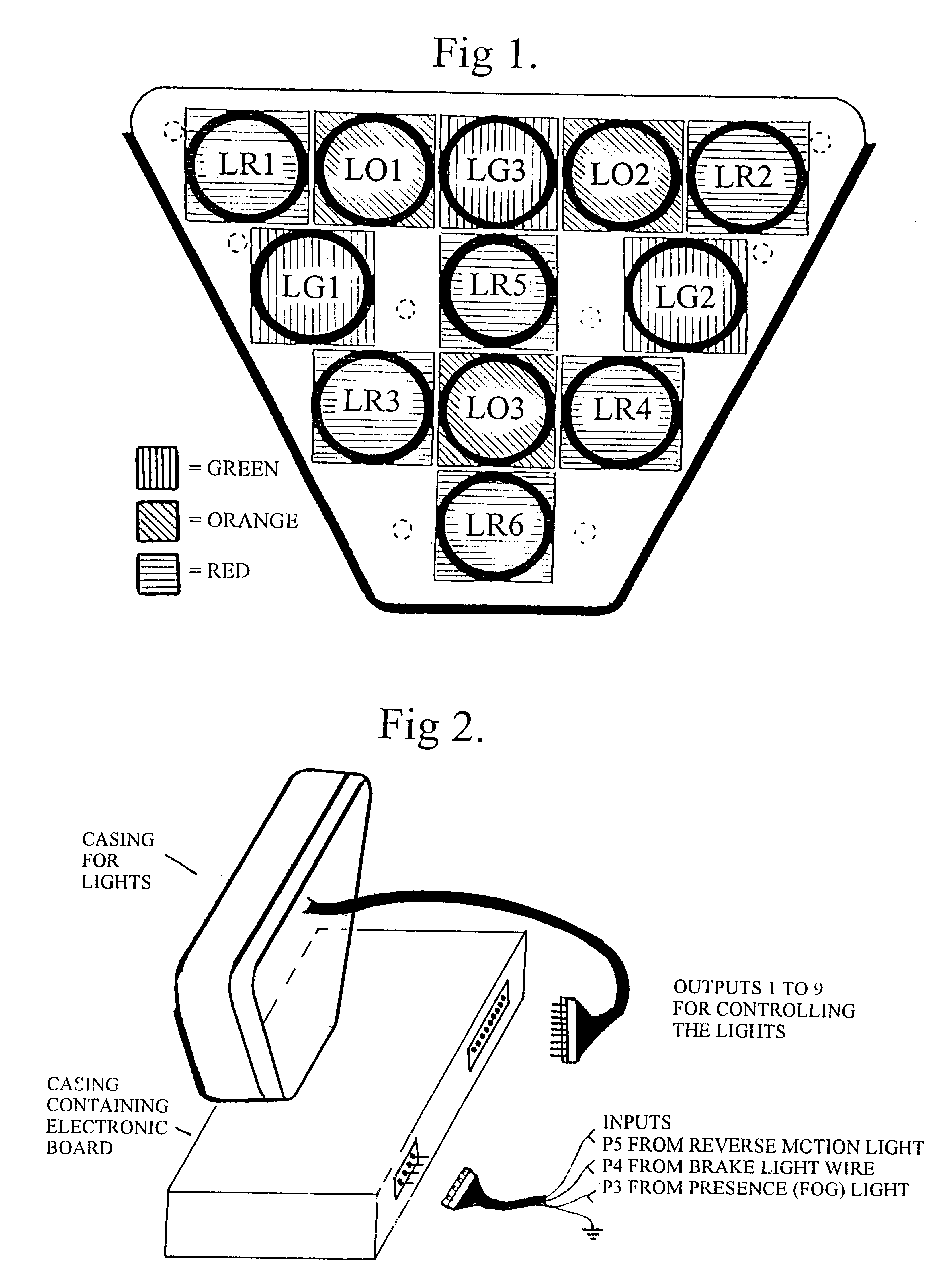
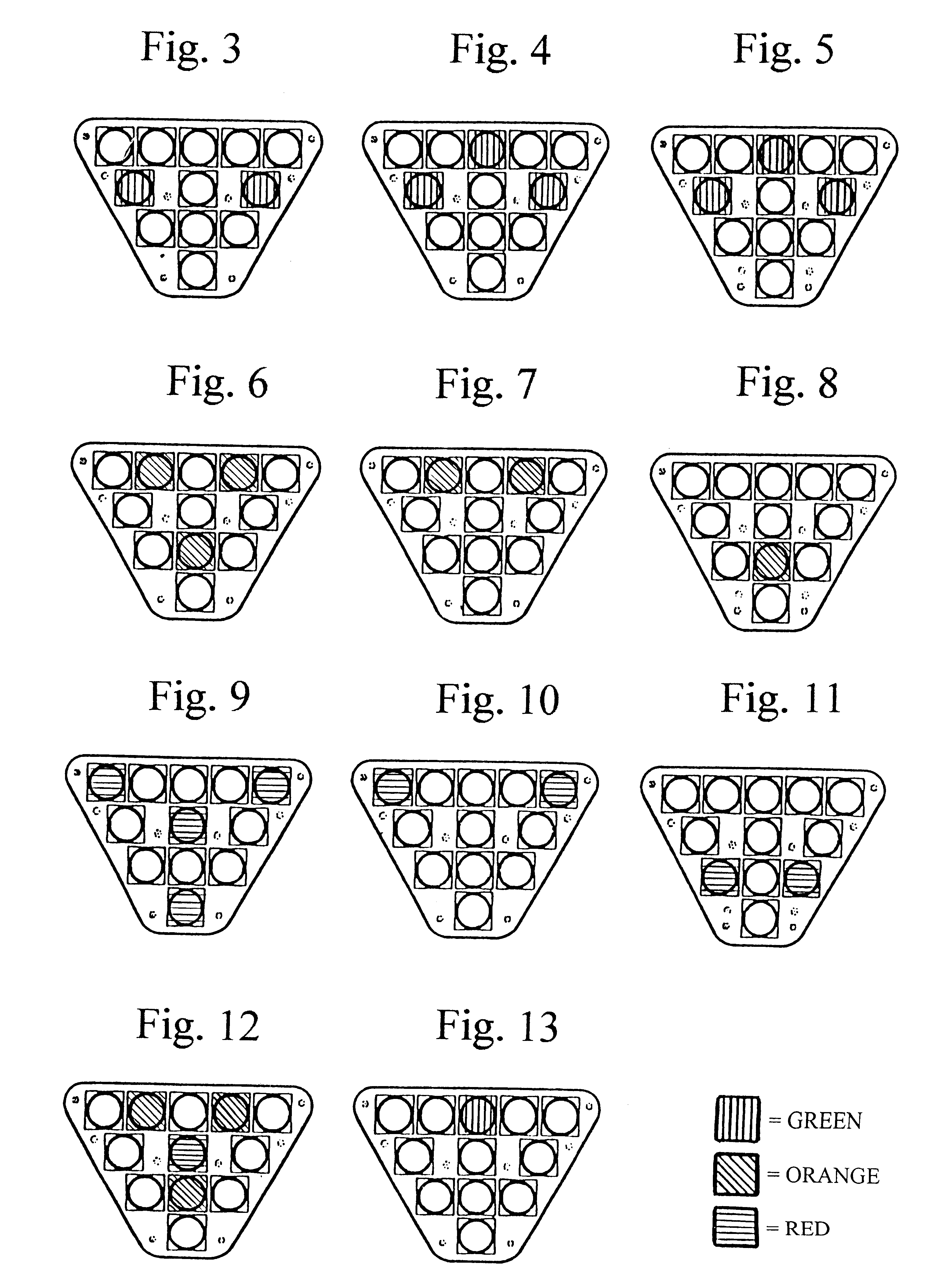
A vehicle signaling display device to be mounted on an automotive vehicle, so that signaling lights of the device are visible for drivers of following vehicles, includes orange or amber, red and green lights and includes a system specifically designed to count speed sensor pulses for measuring speed of any vehicle of any make and model on which the device is installed, for controlling the signaling lights in accordance with the speed of the vehicle and regardless of operation and position of accelerator pedal of the vehicle, in order to perform a set of standardized operations of the signaling lights for dynamically preventing traffic crashes. The device (a) turns on a distinct arrangement of a number of lights of the signaling lights for indicating different ranges of the speed of the vehicle so that a red light of the signaling lights remains lit without flashing regardless of braking as advanced stop sign indicating very low speed or stationary state of the vehicle, orange lights of the signaling lights remain lit indicating low speed of the vehicle and green lights remain lit indicating forward motion with constant speed; (b) flashes orange lights whenever the speed of the vehicle is reduced by a standardized value without braking; (c) flashes red lights whenever the speed of the vehicle is reduced by the standardized value by braking; (d) flashes green lights to indicate acceleration by the standardized value; so that as the rate of deceleration increases, the red or orange lights flash faster.

Description

This invention is a colour coded rear lighting system for motor vehicles.DISCUSSION OF THE RELATED ARTThere are prior art which try to indicate the rate of the deceleration of a vehicle without relying on mechanical deceleration detectors [U.S. Pat. No. 5,481,243 and GE Pat. No. DE 4236395 A1]. One of the outstanding features of the present invention is that it measures speed of vehicle on which it is installed by internationally standardized unit (eg. km / h) and flashes a light when speed of the vehicle is varied by a standardized speed difference.Dynamic Traffic Light takes the place of centre high mounted stop lamps on motor vehicles, since the brake lighting system presently used on vehicles is too primitive and too static.It is primitive because it has a single and simple function which does not precisely reflect the changes of speed of leading vehicles. If leading driver simply reduces pressing the gas pedal and does not brake at all, speed of his / her vehicle drops. In many cas...

Claims


Application Information

Patent Timeline
IPC IPC(8): B60Q1/44
CPCB60Q1/444
Inventor KASHEFY, HAMID R
Owner KASHEFY HAMID R
Learn More