Low speed pulsating showerhead

a showerhead and low-speed technology, applied in the field of showerheads, can solve problems such as the rotation of the shutter

Active Publication Date: 2013-02-05
WATER PIK INC
View PDF970 Cites 136 Cited by
  • Summary
  • Abstract
  • Description
  • Claims
  • Application Information

AI Technical Summary

Problems solved by technology

Rotation of the turbine may cause rotation of the shutter.

Method used


Image

  • Low speed pulsating showerhead
  • Low speed pulsating showerhead
  • Low speed pulsating showerhead

Examples


first embodiment

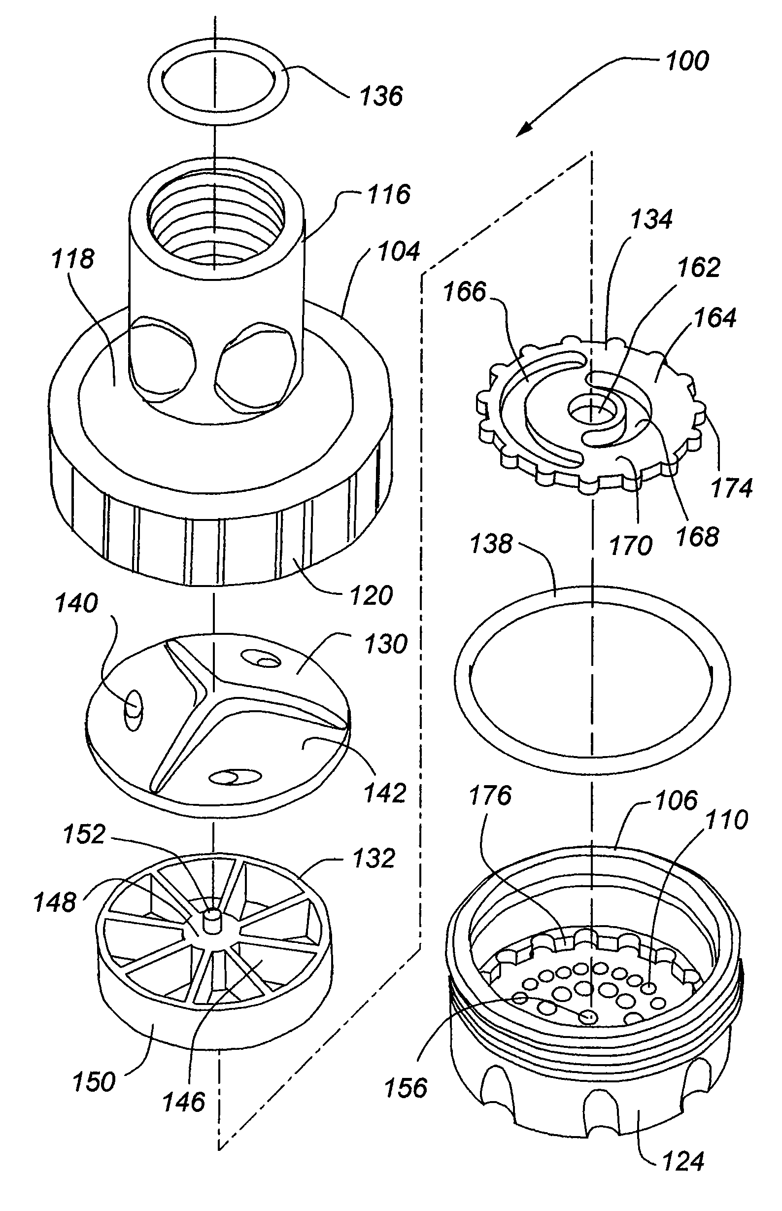
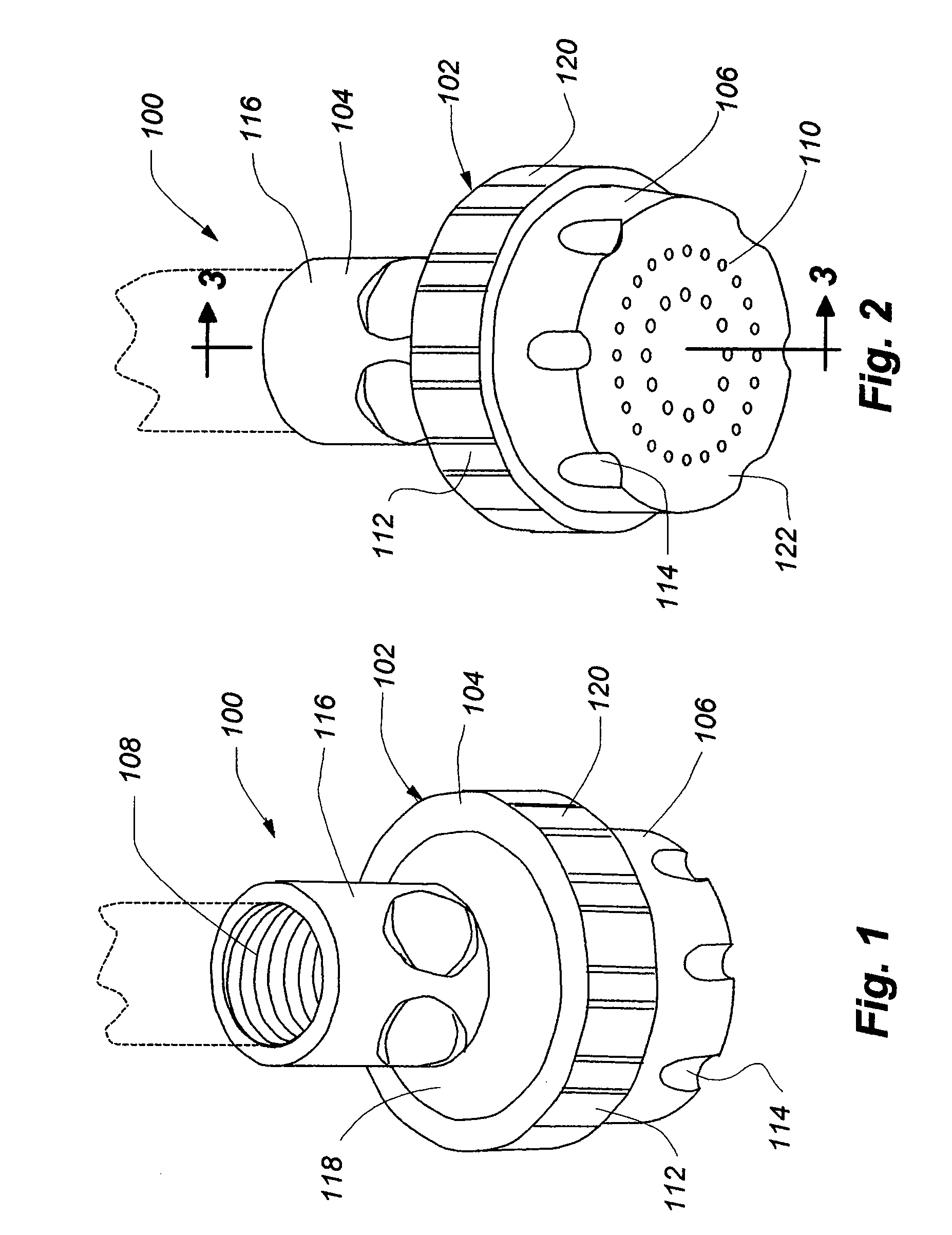
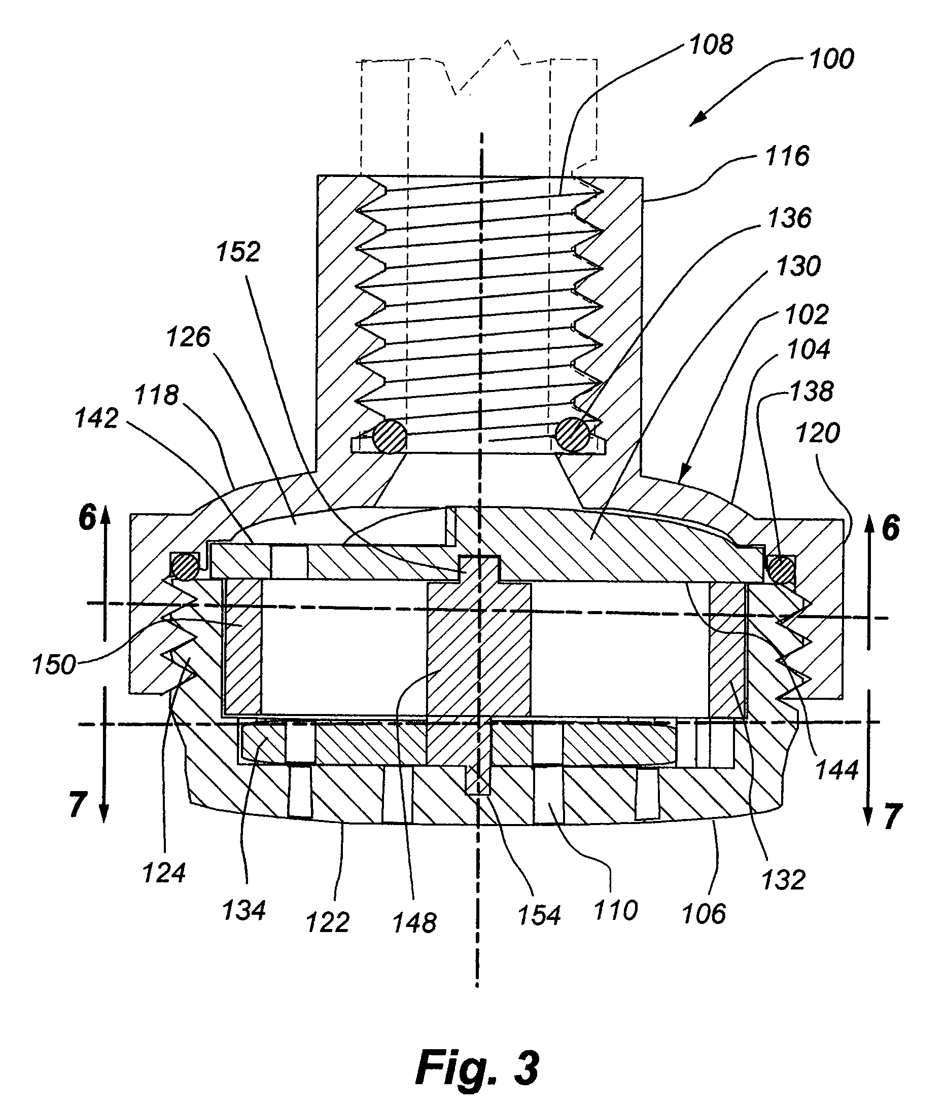
[0041]FIGS. 1-15 depict various views of a showerhead 100. With reference to FIGS. 1 and 2, the showerhead 100 may include a housing 102. The housing 102 may be formed from upper and lower housing portions 104, 106. The upper housing portion 104 may include a fluid inlet for receiving fluid from a fluid source. The upper housing portion 104 may further include threads 108 proximate the fluid inlet for threadedly joining the showerhead 100 to a shower pipe, flexible arm, hose connector, arm assembly, or other device for conveying fluid, such as water, (i.e., a fluid source) to the showerhead 100. Although shown as threadedly joined to the fluid conveying device, the showerhead 100 may be attached to the fluid conveying device using any known connection method or combination of methods, including, but not limited to, press fitting, clamping, welding, and so on. The lower housing portion 106 may include one or more fluid outlets 110 in selective fluid communication with the fluid inlet...

second embodiment

[0065]FIGS. 16-25 depict various views of a showerhead 200. The second showerhead 200 is similar in structure and operation to the first showerhead 100 and like numbers for the second showerhead 200 may be used for similar or like elements of the first showerhead 100. Like the first showerhead 100, the second showerhead 200 may include a turbine 132, a jet disk 130, a shutter 134 and a housing 102. In this particular embodiment, the shutter 134 may include one fluid opening 202 that extends about two-thirds the way around the shutter 134, as shown, for example, in FIGS. 19-20. The showerhead 200 may also include one or more seal members 136, 138, such as a fluid inlet seal member 136 and housing seal member 138 as shown, for example, in FIGS. 18-20. The fluid inlet seal member 136 and the housing seal member 138 may be similar to the corresponding seal members 136, 138 described for the first showerhead 100.

[0066]Like the first embodiment, the housing 102 for the second showerhead 2...


PUM


Abstract

A showerhead may include a housing, a jet disk, a turbine, and a shutter. The housing may include a fluid inlet, at least one fluid outlet, and a chamber in fluid communication with the inlet and one or more outlets. The jet disk, turbine, and shutter may be placed in the cavity. The shutter may include at least one opening. The shutter may selectively cover and uncover fluid outlets, thus selectively fluidly connecting the fluid outlets with the chamber. Water flowing through the housing causes the turbine to spin. As the turbine spins, the shutter rotates at a slower speed than the turbine to produce a periodic interruption of water flow through the outlets by covering and uncovering the outlets as the shutter rotates within the housing.

Description

CROSS-REFERENCE TO RELATED APPLICATIONS[0001]This application claims the benefit under 35 U.S.C. §119(e) to U.S. Provisional Application No. 60 / 882,441, titled “Low Speed Pulsating Shower Head” and filed on Dec. 28, 2006, which is hereby incorporated by reference herein in its entirety.BACKGROUND OF THE INVENTION[0002]1. Field of the Invention[0003]The present invention relates generally to showerheads, and more specifically to pulsating showerheads.[0004]2. Background Art[0005]Generally, showerheads are used to direct water from the home water supply onto a user for personal hygiene purposes. Showers may provide an alternative to bathing in a bath tub.[0006]In the past, bathing was the overwhelmingly popular choice for personal cleansing. However, in recent years showers have become increasingly popular for several reasons. First, showers generally take less time than baths. Second, showers generally use significantly less water than baths. Third, shower stalls and bath tubs with s...

Claims


Application Information

Patent Timeline
Patent Type & Authority Patents(United States)
IPC IPC(8): B05B3/04
CPCB05B3/04B05B1/18
Inventor LEBER, LELAND C.
Owner WATER PIK INC
Why Eureka
Try Eureka