Haptic feedback controller, method of controlling the same, and method of transmitting messages that uses a haptic feedback controller

a haptic feedback and controller technology, applied in the direction of mechanical control devices, process and machine control, instruments, etc., can solve the problems of inability to provide a haptic feedback controller able to express a wide variety of haptic feedback, inevitable loss of haptic feedback ability, etc., to achieve more realistic feedback, more realistic feedback, and fun to play

Inactive Publication Date: 2006-11-16
FUKOKU CO LTD
View PDF15 Cites 136 Cited by
  • Summary
  • Abstract
  • Description
  • Claims
  • Application Information

AI Technical Summary

Benefits of technology

[0086] When the controlled appliance is a game system (such as a commercial game system or a home game system), it is possible to use the haptic feedback controller according to the present invention in addition to a control lever. By doing so, it is possible to provide more realistic feedback from the game system, which makes games more realistic and exciting.
[0087] When the controlled appliance is a toy (such as a radio-controlled car or a radio-controlled plane), it is possible to use the haptic feedback controller according to the present invention in addition to a control lever. By doing so, it is possible to provide more realistic feedback for the environment in which the toy is located (for example, when a radio-controlled car has fallen into a gutter), which makes the toy more fun to play with.
[0088] When the controlled appliance is a content editing appliance (such as a video editing appliance or an audio editing appliance), it is possible to use the haptic feedback controller according to the present invention as a jog dial, a shuttle, or the like on a control panel. By doing so, it is possible to use the content editing appliance more intuitively, which improves the usability of the content editing appliance.
[0089] When the controlled appliance is a means of transport (for example, a car, a train, a ship, or an aircraft), the haptic feedback controller according to the present invention can be used on a control panel. By doing so, it is possible to operate the control panel more intuitively, which improves the usability of the control panel. Since it is possible to provide the haptic feedback controller with a variety of functions, the number of buttons and knobs can be reduced, so that the interior of the means of transport can be made simpler.
[0090] When the controlled appliance is a machine tool (for example, a cutting apparatus, a press apparatus, or a drilling machine), the haptic feedback controller according to the present invention can be used on a control panel. By doing so, it is possible to operate the machine tool more intuitively, which improves the usability of the machine tool. As one example, when the machine tool is a cutting apparatus, since it is possible to determine the cutting conditions while feeling the stress received by the cutting blade, after such determination it is possible to always carry out cutting under optimal conditions, which makes it possible to improve the quality of cut products and to extend the lifespan of the cutting blade.
[0091] When the controlled appliance is a medical appliance (such as a surgery assisting apparatus or an endoscope), it is possible to use the haptic feedback controller according to the present invention as a knob for controlling the movement of a knife or an endoscope. By doing so, it is possible to operate the medical appliance more intuitively, so that more appropriate medical procedures can be carried out than before.

Problems solved by technology

However, in the haptic feedback controller 1200, since a belt transmission mechanism with large backlash is present between the knob 1202 and the DC motor 1208, there has been the problem that there is inevitably a loss in the ability to express haptic feedback.
This means that there has been the problem that it has not been possible to provide a haptic feedback controller able to express a wide variety of haptic feedback.

Method used


Image

  • Haptic feedback controller, method of controlling the same, and method of transmitting messages that uses a haptic feedback controller
  • Haptic feedback controller, method of controlling the same, and method of transmitting messages that uses a haptic feedback controller
  • Haptic feedback controller, method of controlling the same, and method of transmitting messages that uses a haptic feedback controller

Examples


first embodiment

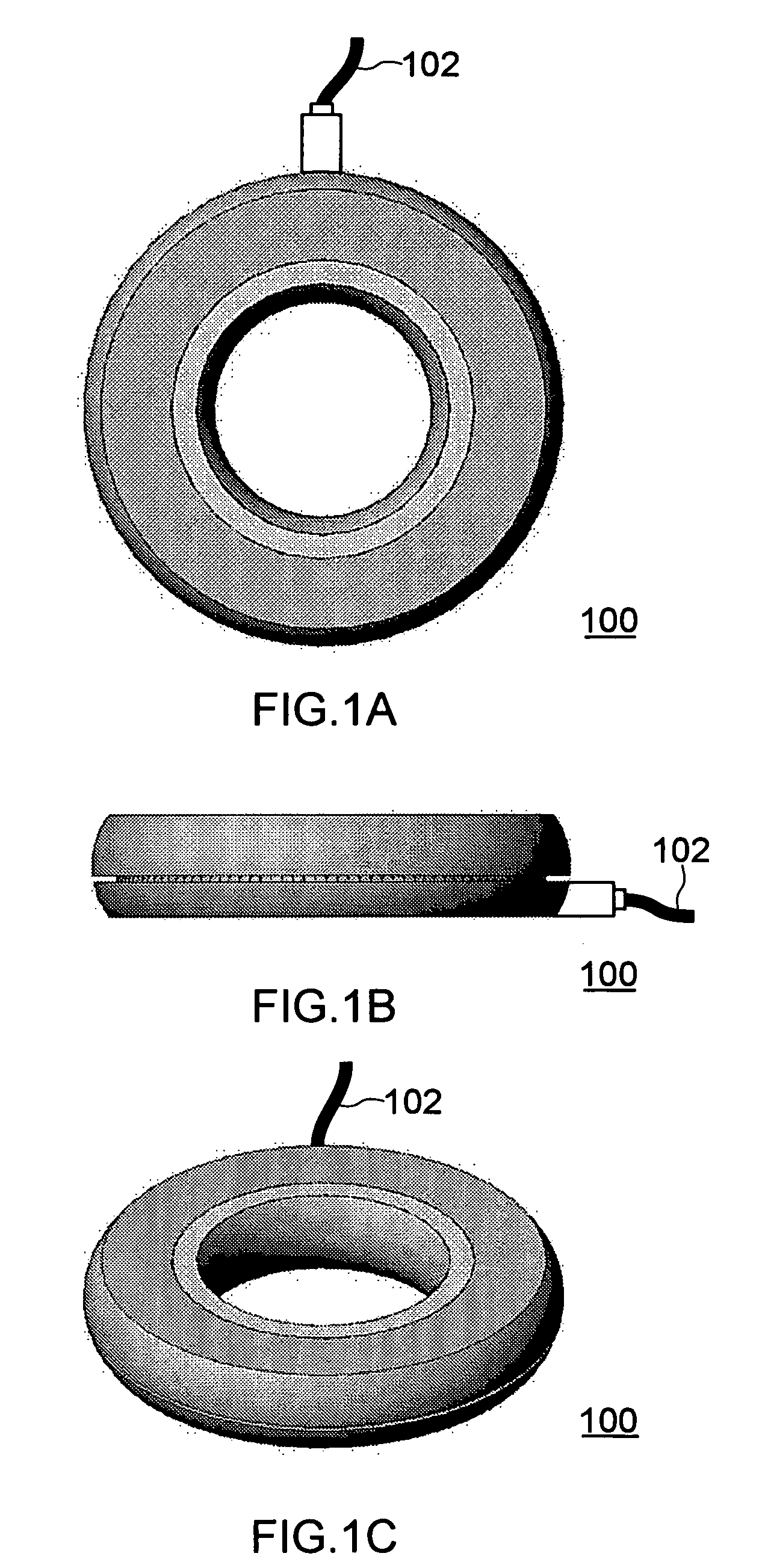
[0126]FIG. 1 is a series of diagrams useful in explaining a haptic feedback controller 100 according to a first embodiment. FIG. 1(A) is a plan view of the haptic feedback controller 100, FIG. 1(B) is a right-side elevation of the haptic feedback controller 100, and FIG. 1(C) is a perspective view of the haptic feedback controller 100.

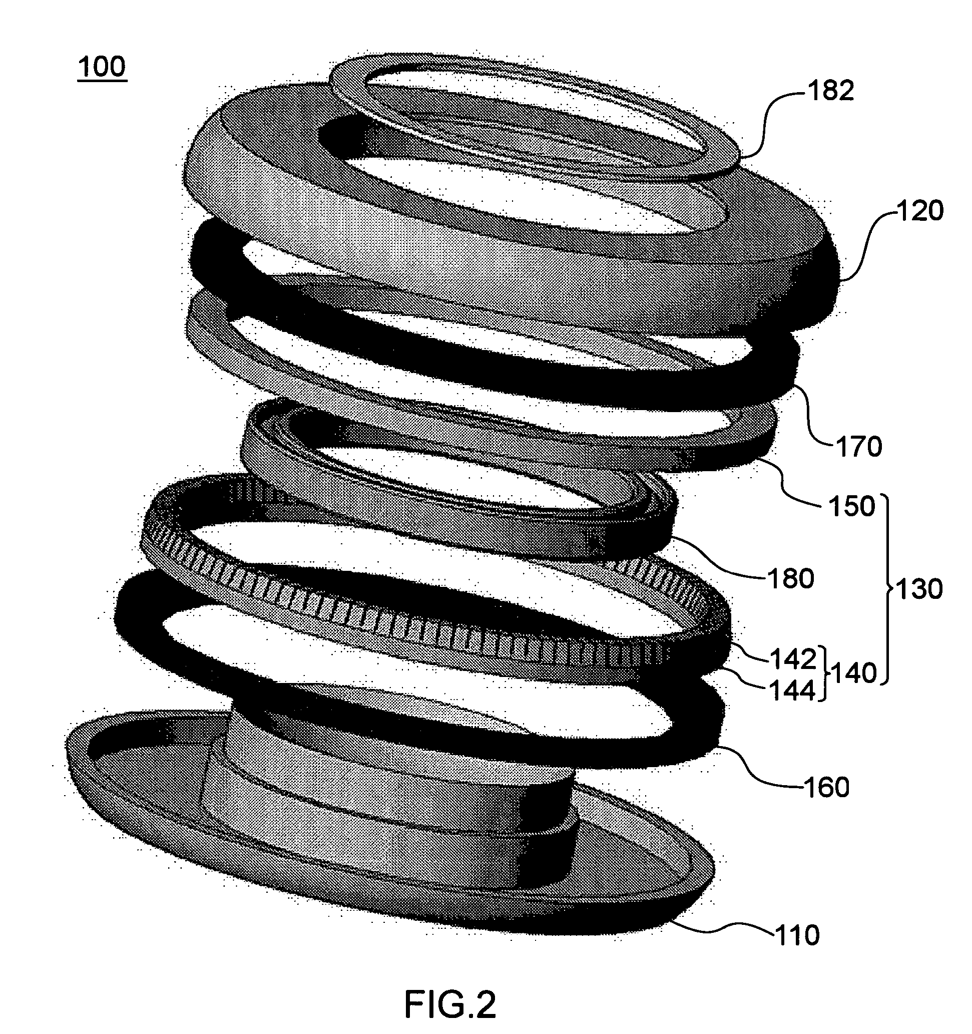
[0127]FIG. 2 is an exploded perspective view useful in explaining the haptic feedback controller 100 according to the first embodiment.

[0128]FIG. 3 is a diagram useful in explaining a state in which the haptic feedback controller 100 according to the first embodiment is used.

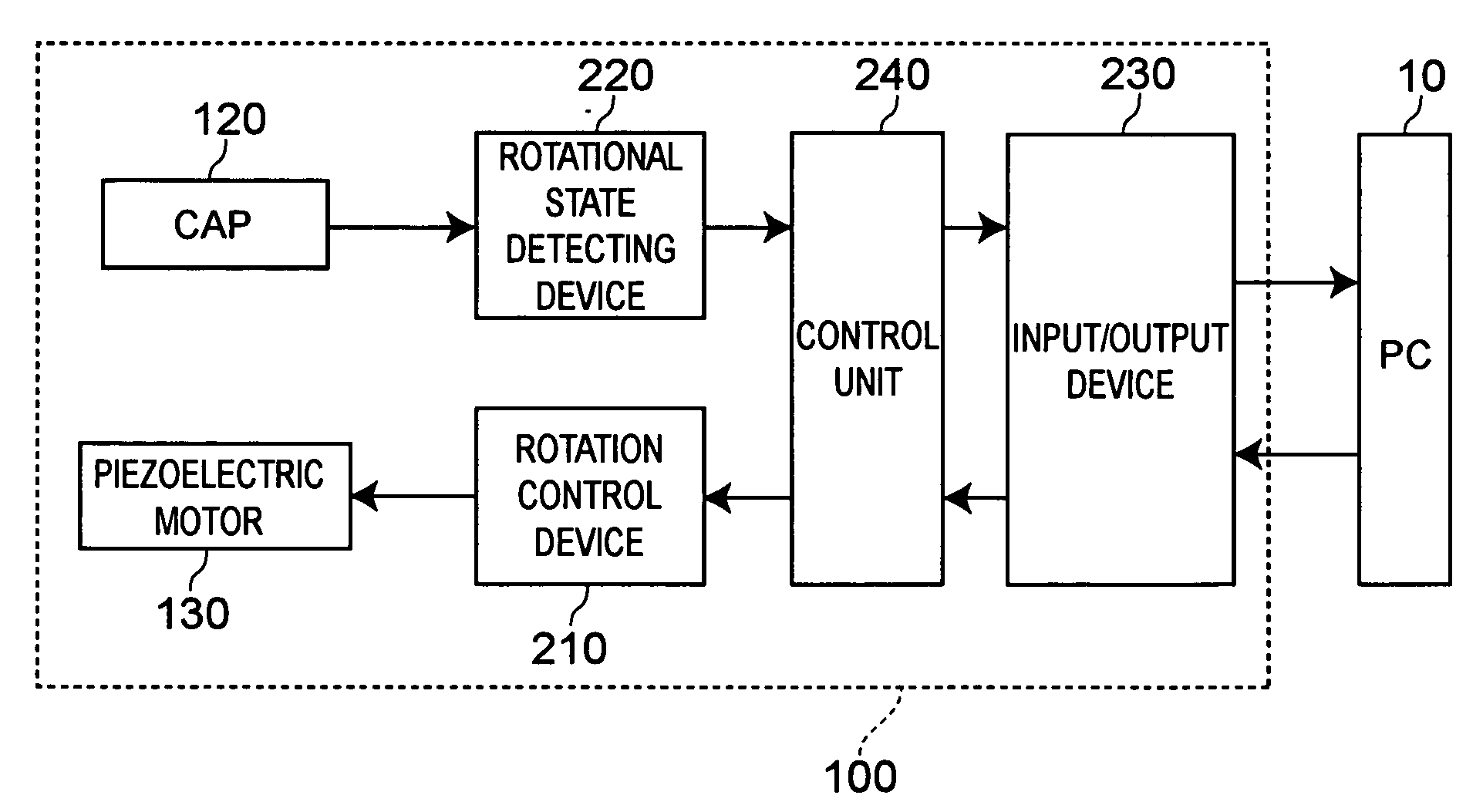
[0129]FIG. 4 is a block diagram useful in explaining the functions of the haptic feedback controller 100 according to the first embodiment.

[0130]FIG. 5 is a series of diagrams useful in explaining the haptic feedback controller 100 according to the first embodiment. FIG. 5(A) is a cross-sectional view of the haptic feedback controller 100 and FIG. 5(B) is an enlarged view of pa...

second embodiment

[0190]FIG. 8 is a series of diagrams useful in explaining a haptic feedback controller 100a according to a second embodiment. FIG. 8(A) is a cross-sectional view of the haptic feedback controller 100a according to the second embodiment and FIG. 8(B) is an enlarged view of part of FIG. 8(A).

[0191] The haptic feedback controller 100a according to the second embodiment fundamentally has the same construction as the haptic feedback controller 100 according to the first embodiment, but the construction of the contact switches differs to that used in the haptic feedback controller 100 according to the first embodiment. That is, in the haptic feedback controller 100a according to the second embodiment, as shown in FIGS. 8(A) and 8(B), a switch member 112 is further provided on an inner circumferential part of a base 110a, and four contact switches 194a are disposed apart from one another in the circumferential direction on an inner circumferential surface of the base 110a between the base...

third embodiment

[0195]FIG. 9 is a partial cross-sectional view useful in explaining a haptic feedback controller 100b according to a third embodiment.

[0196] The haptic feedback controller 100b according to the third embodiment fundamentally has the same construction as the haptic feedback controller 100 according to the first embodiment, but as shown in FIG. 9, the construction differs to the haptic feedback controller 100 according to the first embodiment in that a cap 120a composes an inner circumferential surface of the haptic feedback controller. In accordance with this, the position at which a ball bearing 180a is disposed and the positions at which an encoding barcode 190a and an optical sensor unit 192a are disposed also differ.

[0197] In this way, the haptic feedback controller 100b according to the third embodiment differs to the haptic feedback controller 100 according to the first embodiment in that the cap 120a composes the inner circumferential surface of the haptic feedback controlle...


PUM


Abstract

A haptic feedback controller 100 according to the present invention is a haptic feedback controller that controls a controlled appliance and includes a base 110, a cap 120, a piezoelectric motor 130, a rotation control device, and a rotational state detecting device.
According to haptic feedback controller 100 of the present invention, the piezoelectric motor 130 that can produce a large torque even when rotating at low speed is used, so that even when the cap 120 is rotated at low speed, sufficiently large haptic feedback can be applied to the cap 120. Also, since the base 110 and the cap 120 are respectively fixed to the stator 140 and the rotor 150 of the piezoelectric motor 130, there is no backlash. As a result, according to the present invention it is possible to provide a haptic feedback controller for which there is no loss in the ability to express haptic feedback, so that a wide variety of haptic feedback can be expressed.

Description

TECHNICAL FIELD [0001] The present invention relates to a haptic feedback controller, a method of controlling the same, and a method of transmitting messages that uses a haptic feedback controller. BACKGROUND ART [0002]FIG. 20 is a series of diagrams useful in explaining a conventional haptic feedback controller 1100. FIG. 20(A) is a perspective view showing the haptic feedback controller 1100 and FIG. 20(B) is an exploded perspective view showing the haptic feedback controller 1100. FIG. 21 is a diagram showing a control panel 1150 equipped with the haptic feedback controller 1100. FIG. 22 is a block diagram of the control panel 1150. [0003] As shown in FIG. 20B, the haptic feedback controller 1100 includes a DC motor 1108 and a knob 1102 that is coupled to a rotating shaft of the DC motor 1108. The DC motor 1108 is disposed in an internal space enclosed by a top case 1104 and a bottom case 1106 of the haptic feedback controller 1100. As shown in FIG. 21, the knob 1102 is rotatable...

Claims


Application Information

Patent Timeline
Patent Type & Authority Applications(United States)
IPC IPC(8): H02N2/00G06F3/033G06F3/0362
CPCG05G1/10G05G5/03G06F3/016B60K2350/102H02N2/163B60K37/06G06F3/0362B60K2370/126B60K2370/158
Inventor SUZUKI, TAKAHIKOKODAIRA, TAKESHI
Owner FUKOKU CO LTD
Why Eureka
Try Eureka