A syringe

a technology of syringes and syringes, which is applied in the field of syringes, can solve the problems of user difficulty in seeing, distraction of attention, and devices that are more expensive and heavier than traditional syringes

a technology of syringes and syringes, which is applied in the field of syringes, can solve the problems of user difficulty in seeing, distraction of attention, and devices that are more expensive and heavier than traditional syringes

US20190015597A1Active Publication Date: 2019-01-17GALDERMA HLDG SA

Image

  • A syringe
  • A syringe

Examples


Embodiment Construction

[0052]A syringe 100 according to an embodiment of the invention is shown in an exploded view in FIG. 1. The syringe comprises a barrel 1, a plunger 2 moveably arranged within the barrel 1 and a plunger rod 3 for driving the plunger 2. The plunger rod is further provided with a thumb plate 14 for activation of the plunger rod 3. The plunger rod 3 is adapted to drive the plunger 2, i.e. to engage the plunger 2 such that the plunger 2 may preferably be moved in both directions through the barrel. Suitable engagement means may be provided to allow for this engagement. The syringe 100 further comprises a needle 16. The syringe is further provide with a finger grip 17 arranged at the barrel.

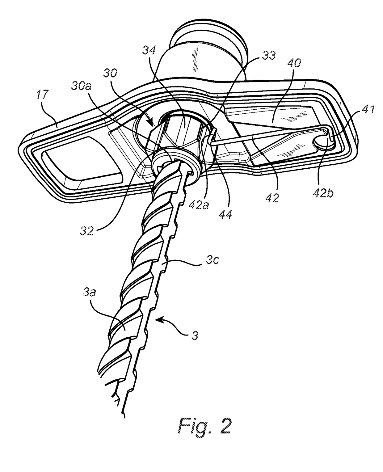
[0053]The syringe further comprises a first engagement member 30 arranged at the plunger rod 3, shown in more detail in FIG. 2. The first engagement member 30 has a substantially circular, or annular shape, i.e. may be described as having a wheel shape. Further, the first engagement member comprises a ...


PUM


Abstract

A syringe including a barrel, a plunger moveably arranged within said barrel and a plunger rod for driving said plunger is provided. The syringe includes a first engagement member arranged at the plunger rod such that a longitudinal movement of the plunger rod yields a rotational movement of said first engagement member, said first engagement member including a grooved surface, and a second engagement member arranged at the barrel to engage with said grooved surface of the first engagement member such that feedback is given to a user as the plunger rod is moved relative to the barrel for driving said plunger. Wherein, for a given distance D travelled by the plunger rod relative to the barrel, a point of the grooved surface of the first engagement member moves a distance d, wherein d≥D.

Description

TECHNICAL FIELD[0001]The present invention generally relates to syringes, and more particularly to a syringe that is able to provide a user with feedback during use.TECHNICAL BACKGROUND[0002]When a user of a medical syringe administers a substance, it is common, in particular within certain areas of treatment, to distribute the total volume carried by the syringe over an area. Some examples of such areas of treatment are dermatology, plastic surgery, cosmetic surgery, and odontology. The distribution is for instance done by inserting the needle of the syringe just beneath and approximately in parallel with the skin surface and then administering the substance while withdrawing the needle. Another way is to administer the substance at several anatomic locations within a limited area, i.e. to administer a fraction of the total volume at each location.[0003]In these, and other, methods of distributing the substance it is an advantage if the syringe is provided with some kind of dosing ...

Claims


Application Information

Patent Timeline
17 Jan 2019
Publication
US20190015597A1
IPC
A61M5/315; A61M5/31
CPC
A61M5/31578; A61M5/3148; A61M2205/582; A61M5/31575; A61M2205/581; A61M5/31568; A61M5/178; A61M5/3158
Inventors
HOLMQVIST, ANDERS; BLOMQVIST, MAX