Pneumatic radial tire including beveled acute angle corner portions

a radial tire and pneumatic technology, applied in the field of pneumatic radial tires, can solve the problems of low tire noise level, difficult to provide tires, and deterioration of tire noise level

Inactive Publication Date: 2001-04-10
BRIDGESTONE CORP
View PDF29 Cites 38 Cited by
  • Summary
  • Abstract
  • Description
  • Claims
  • Application Information

AI Technical Summary

Problems solved by technology

However, these performances required in the tire conflict with each other in the pattern design, so that it is very difficult to provide a tire simultaneously establishing excellent drainage property in the running on wet road surface, steering stability in the running

Method used


Image

  • Pneumatic radial tire including beveled acute angle corner portions
  • Pneumatic radial tire including beveled acute angle corner portions
  • Pneumatic radial tire including beveled acute angle corner portions

Examples


Embodiment Construction

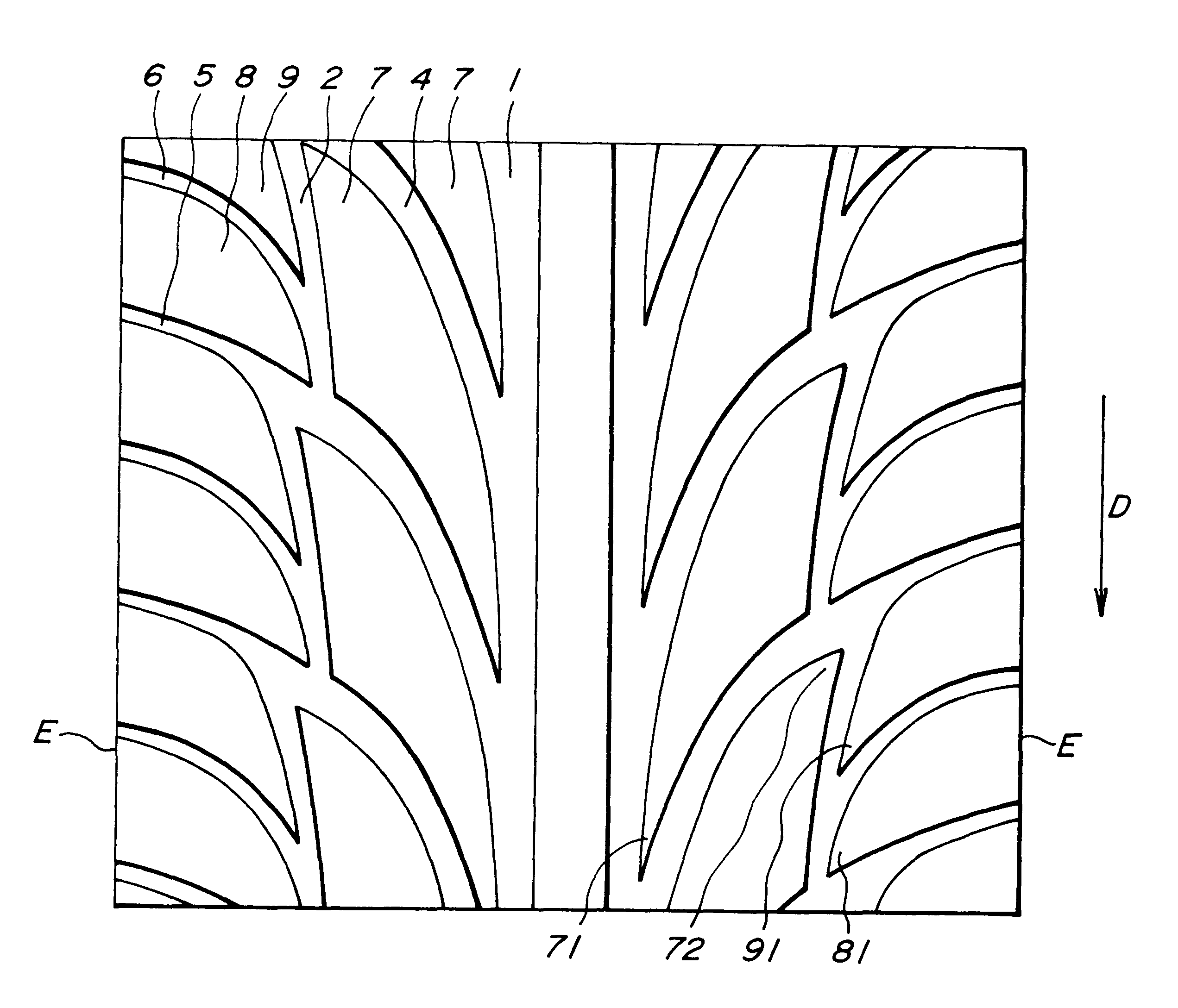
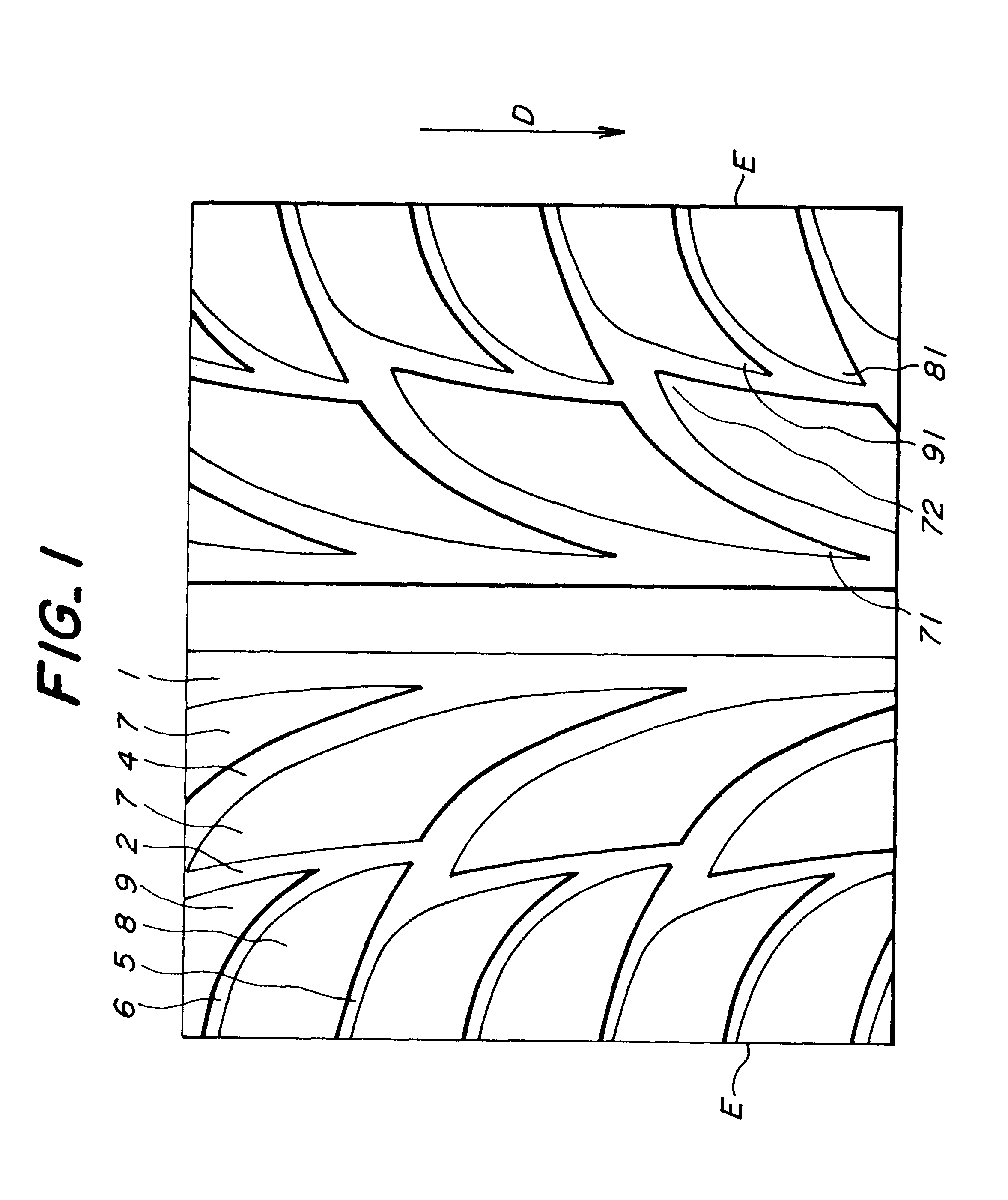
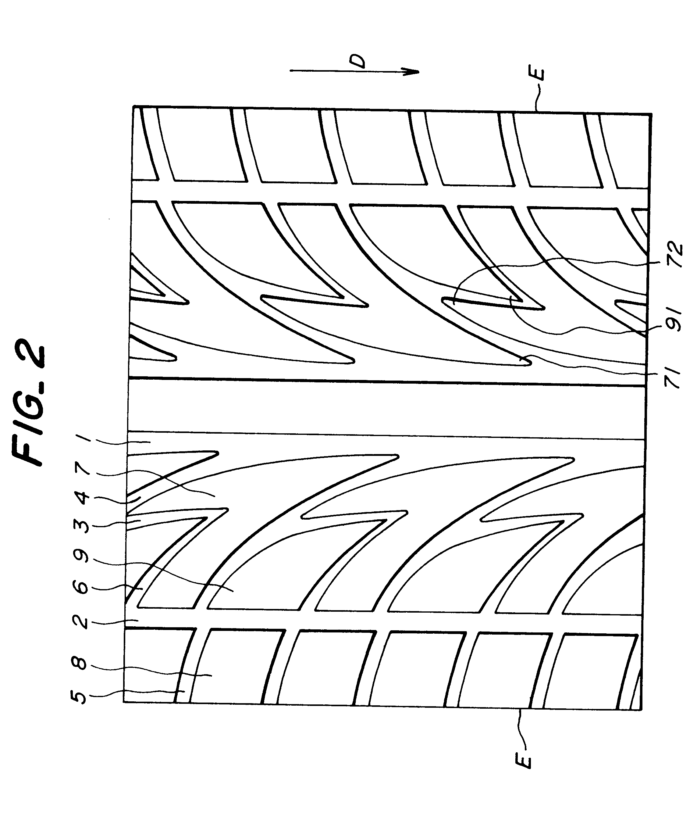
In the pneumatic radial tire according to the invention, the tread pattern has the aforementioned structure wherein many blocks are formed at intervals in circumferential and axial directions of the tire by plural circumferential grooves and plural directional slant grooves. At least a part of the directional slant grooves is branched from a circumferential groove arranged in the vicinity of a center of the tread pattern among said circumferential grooves and extends toward and is opened at an end of a ground contact region of the tread. At least a part of corner portions of each of the blocks forms an acute angle of 10-60.degree. defined by the circumferential groove and the directional slant groove, and a surface of the corner portion of the block having an acute angle of 10-60.degree. is beveled over a distance of 10-30 mm from a tapered end thereof in a longitudinal direction to gradually shallow from the tapered end toward a width widened portion of the block in both stepping-i...


PUM


Abstract

A pneumatic radial tire for passenger car has a directional tread pattern comprising many blocks formed in a tread portion by a plurality of circumferential grooves extending in a circumferential direction of the tire and a plurality of directional slant grooves obliquely extending with respect to the circumferential direction, wherein at least a part of the directional slant grooves is branched from the circumferential groove near to the pattern center and extends toward and is opened at an end of a ground contact region of the tread, and at least a part of corner portions of each of the blocks forms an acute angle of 10-60° defined by the circumferential groove and the directional slant groove; and a surface of the corner portion of the block having an acute angle of 10-60° is beveled over a distance of 10-30 mm from a tapered end thereof in a longitudinal direction so as to gradually shallow from the tapered end toward a width widened portion of the block in both stepping-in and kicking-out sides of the block.

Description

1. Field of the InventionThis invention relates to a pneumatic radial tire, and more particularly to a pneumatic radial tire for passenger car having high running-performances and provided with a directional tread pattern specifying a rotating direction of the tire when mounted onto a vehicle. Many blocks are formed in the trend pattern at given intervals in a circumferential direction of the tire by a plurality of circumferential grooves arranged at given intervals in an axial direction of the tire and extending in parallel to or substantially in parallel to the circumferential direction. A plurality of directional slant grooves arranged in the trend pattern at given intervals in the circumferential direction and obliquely extending with respect to the circumferential direction.The term "directional slant groove" used herein means a groove obliquely extending with respect to the circumferential direction and specifying a rotating direction (forward direction) of the tire to precede...

Claims


Application Information

Patent Timeline
IPC IPC(8): B60C11/03B60C11/13B60C11/11
CPCB60C11/0302B60C11/11B60C11/13B60C2011/0388B60C2011/0374
Inventor HIMURO, YASUO
Owner BRIDGESTONE CORP
Why Eureka
Try Eureka