Spoke centered puller tab crankshaft damper hub

a crankshaft and hub technology, applied in the direction of spring/damper, vibration suppression adjustment, flywheel, etc., can solve the problems of increasing the cost of the hub, the possibility of missed machining operations, and the inability to easily remove the damper hub from the crankshaft to which it is attached, so as to facilitate the removal of the damper hub

Inactive Publication Date: 2001-04-17
METALDYNE MACHINING & ASSEMBLY
View PDF14 Cites 23 Cited by
  • Summary
  • Abstract
  • Description
  • Claims
  • Application Information

AI Technical Summary

Benefits of technology

It is an object of the present invention to provide a damper hub having openings formed in the spokes...

Problems solved by technology

Current hubs are difficult to remove from the crankshaft when repairs, maintenance or other work needs to be performed on the engine.
The manufacture of this type of hub has required two machining operations (drilling and tapping) which increased the cost of ...

Method used


Image

  • Spoke centered puller tab crankshaft damper hub
  • Spoke centered puller tab crankshaft damper hub
  • Spoke centered puller tab crankshaft damper hub

Examples


Embodiment Construction

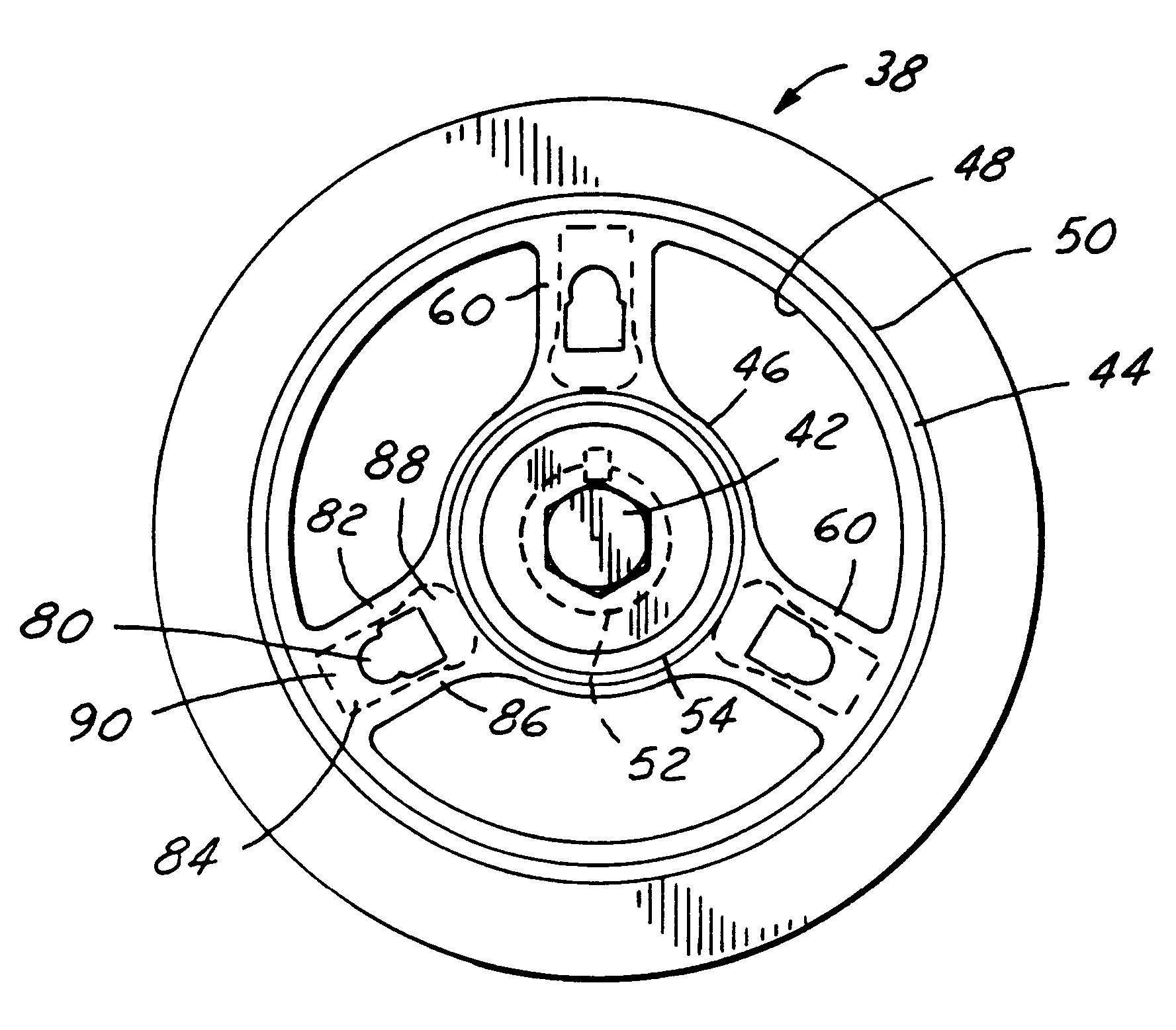
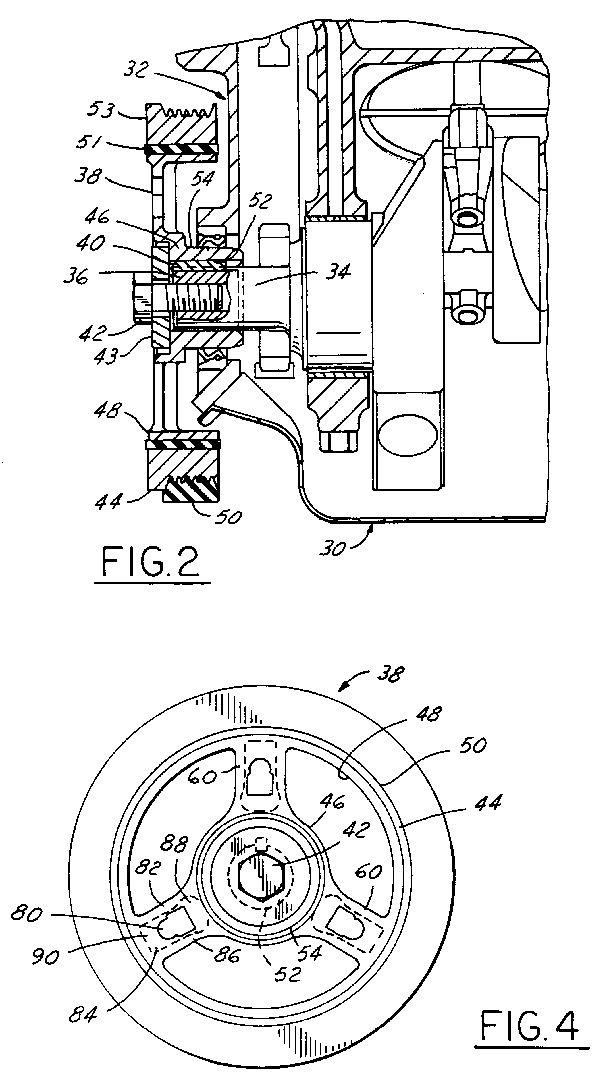
FIG. 2 illustrates an engine assembly 30 having a front face 32 and an engine crankshaft 34 having an end 36 extending through the front face 32 of the engine assembly 30. A damper hub 38 is mounted to an end 36 of the crankshaft 34. A damper 40 is preferably positioned at the crankshaft end 36 in order to minimize noise, vibration, and harshness which can be transmitted through the crankshaft 34 engine assembly 30. As is well known, the hub 38, which is driven by the crankshaft 34, is in communication with a belt or chain to drive other pumps or components. The hub 38 is securely mounted to the crankshaft 34 by a securing means 42 such as a bolt or the like to prevent disengagement of the hub 38 from the engine crankshaft 34. A washer 43 is disposed between the securing means and the hub 38.

The hub 38 includes an outer rim portion 44 and a center portion 46. The outer rim portion 44 has an inner periphery 48 and an outer periphery 50. The outer periphery 50 of the hub 38 is designe...


PUM

PropertyMeasurementUnit
Shapeaaaaaaaaaa

Abstract

A crankshaft damper hub (10) for attachment to an engine crankshaft (34) has an outer rim (44) and a center portion (46). The center portion (46) has a passageway (56) formed therethrough for receipt of an engine crankshaft (34). A plurality of spokes (60) extend between the outer rim (44) and the center portion (46). An opening (66) is formed in each of the plurality of spokes (60) with a tab (72) formed therein for engagement with a tool to facilitate removal of the hub (10) from the crankshaft (34).

Description

The invention relates generally to a damper hub for a crankshaft. More specifically, the present invention relates to a crankshaft damper hub with spoke centered puller tabs to allow the hub to be more easily removed from the crankshaft.1. Background ArtIt is well known in the automotive industry to utilize crankshaft damper hubs to reduce to overall noise transmitted through an engine assembly. The crankshaft damper hub is typically positioned at or near the front of the engine assembly and drives a plurality of other devices similarly located. Current hubs are difficult to remove from the crankshaft when repairs, maintenance or other work needs to be performed on the engine. One example of these hubs utilizes threaded puller holes formed therein to assist in their removal. The manufacture of this type of hub has required two machining operations (drilling and tapping) which increased the cost of the hub and the possibility of missed machining operations.Other prior damper hub desi...

Claims


Application Information

Patent Timeline
IPC IPC(8): B25B27/02F16F15/121F16F15/126F16F15/30F16F15/315
CPCB25B27/02F16F15/315F16F15/126Y10T29/53943
Inventor HENDRIAN, MICHAEL D.
Owner METALDYNE MACHINING & ASSEMBLY
Why Eureka
Try Eureka