Bushing base with mounted nozzles

Inactive Publication Date: 2001-04-24
ENGELHARD CLAL SAS
View PDF6 Cites 26 Cited by
  • Summary
  • Abstract
  • Description
  • Claims
  • Application Information

AI Technical Summary

Problems solved by technology

Unfortunately, a deep-drawing method makes it very difficult to obtain a bushing baseplate of thickness having good regularity.
In the context of a deep-drawing method, it is necessary to leave a sufficient volume of metal between two adjacent holes since otherwise metal taken therefrom during the deep-drawing operation can give rise to weak points in the thickness of the baseplate, and guaranteeing such volumes of metal is very diff

Method used


Image

  • Bushing base with mounted nozzles
  • Bushing base with mounted nozzles
  • Bushing base with mounted nozzles

Examples


example 2

The method is as described for Example 1 concerning steps a) to e).

However, thereafter, in a variant there follows an additional step which consists in using a brazing filler paste.

f) Thus, a brazing filler paste of the above-described type is prepared, e.g. based on a platinum-copper powder having 35% by weight copper, dispersed in a polymer binder, the powder constituting about 93% of the filler paste and the binder about 7%, the binder being polybutene, for example, with viscosity of about 200,000 centipoises as measured using the HAAKE RV12 PK 100 viscosity measuring device at temperature of 0.5.degree. C. and rotating at a speed of rotation of 0.8 revolutions per minute.

It is also possible to use as the brazing filler paste, powdered palladium in a polymer binder, the binder representing 14% by weight of the filler paste.

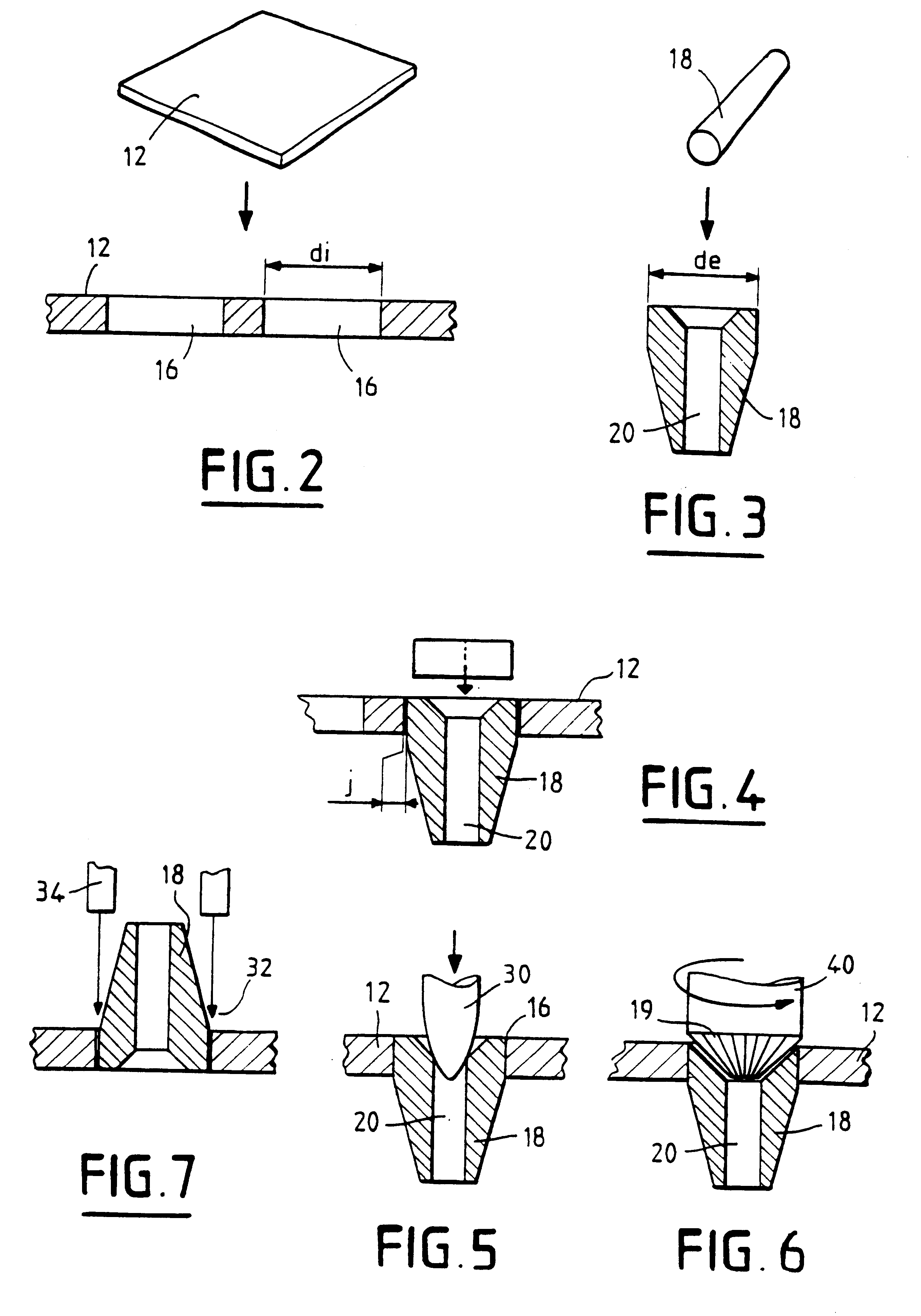
g) A continuous line of brazing filler paste 32 is deposited along each line of tips 18 by means of an automatic dispenser 34 controlled with a needle, e.g. ha...


PUM

PropertyMeasurementUnit
Fractionaaaaaaaaaa
Fractionaaaaaaaaaa
Fractionaaaaaaaaaa

Abstract

The invention relates to a method of manufacturing a bushing baseplate, and to a bushing baseplate. The bushing baseplate is characterized in that it comprises tips (18) constituted by hollow tubular elements of outside diameter slightly smaller than the inside diameter of holes (16) in the plate (12) forming the bushing baseplate, which tips are subjected to a step of being expanded radially relative to their axes. The method is simpler and less expensive.

Description

The present invention relates to a method of manufacturing a bushing baseplate, and also to the bushing baseplate obtained thereby and to the bushing itself. The invention also covers brazing filler pastes as novel substances. More particularly, the invention relates to a method of manufacturing a bushing baseplate for drawing glass fibers, to bushing baseplates obtained thereby, and to brazing filler pastes as novel substances.DESCRIPTION OF THE PRIOR ARTIn the manufacture of glass fiber commonly used for reinforcing plastics materials, the bushing is the most critical tool in the production line since it determines the quality of the final product.The bushing is generally made of an alloy of platinum and rhodium and is in the form of a box into which molten glass is inserted, the box having a baseplate that is perforated by numerous holes. Each of these holes is constituted by a pierced jet known as a "tip" through which the glass flows out to produce a fiber once it has solidifie...

Claims


Application Information

Patent Timeline
IPC IPC(8): B21K21/08B21K21/00B23P15/16C03B37/08C03B37/00
CPCB21K21/08B23P15/16C03B37/0805Y10S72/70Y10S29/004Y10T428/12646Y10T428/12361Y10T29/4994Y10T29/49938Y10T428/12375Y10T29/18Y10T428/12875Y10T83/0481C03B37/08
Inventor GUERLET, JEAN-PAULPOULIQUEN, FRANCKMICHEL, DANIEL
Owner ENGELHARD CLAL SAS
Why Eureka
Try Eureka