Portable air conditioner/beverage container

a portable air conditioner and beverage technology, applied in the field of portable air conditioners/beverage containers, can solve the problems of air not being sufficiently cooled before exiting onto the user of the device, and not having any means to ensure the air quality, etc., to achieve convenient cleaning, convenient use, and efficient operation

Inactive Publication Date: 2001-05-08
COOL GUYZ
View PDF17 Cites 64 Cited by
  • Summary
  • Abstract
  • Description
  • Claims
  • Application Information

AI Technical Summary

Benefits of technology

Another feature of the present invention is a removable insert that allows for easy cleaning of the device.
Another feature of the present invention is the provision of a portable air conditioner / beverage container that is economical, easy to use, and efficient in operation.

Problems solved by technology

While this device aims to function as an air conditioner, it does not have any means to ensure that air passes through a cooling substance, such as ice, before being expelled onto the operator.
Air is not sufficiently cooled before exiting onto a user of the device.

Method used


Image

  • Portable air conditioner/beverage container
  • Portable air conditioner/beverage container
  • Portable air conditioner/beverage container

Examples


third embodiment

A cross-sectional view of the portable air conditioner / beverage container 10B is shown in FIG. 7. The portable air conditioner 10B of FIG. 7 is nearly identical to that disclosed in FIGS. 1-6. However, in FIG. 7 the locations of the air intake vent 36A and the cool air vent 48A have changed. The embodiment in FIG. 7 shows the use of a blade type fan 28A instead of a squirrel cage fan. The flow of air is shown by arrows 58A. Air enters through air intake vent 36A, passes through holes 40 in the separation wall 38, through the ice 46, and is blown out through the cool air vent 48A by the fan 28A. Wall 57 prevents liquid from leaving through the air intake vent 36A.

fourth embodiment

FIG. 8 shows a cross-sectional view of a fourth embodiment according to the present invention. The portable air conditioner / beverage container 70 of FIG. 8 keeps the beverage 110 isolated from the ice 106. This embodiment is particularly useful when the beverage 110 is beer. When the ice 106 melts, it won't water down the beer 110. The operation of the portable air conditioner 70 is substantially the same as the operation of the embodiment disclosed in FIGS. 1-7.

A lid 74 is connected to the container 72 via hinge 76. Snap closure 120 secures the lid 74 to the container 72. The container 72 has a closed bottom 80, a cylindrical side wall 114, and a top 78. Preferably, the side wall 114 is insulated. Within the top 78 there is a beverage intake opening 82. The beverage 110 is poured into the container 72 through the beverage intake opening 82. A piece of rubber 121 around the top 78 of the container 72 forms a seal between the container 72 and the lid 74.

In the interior of the contain...

fifth embodiment

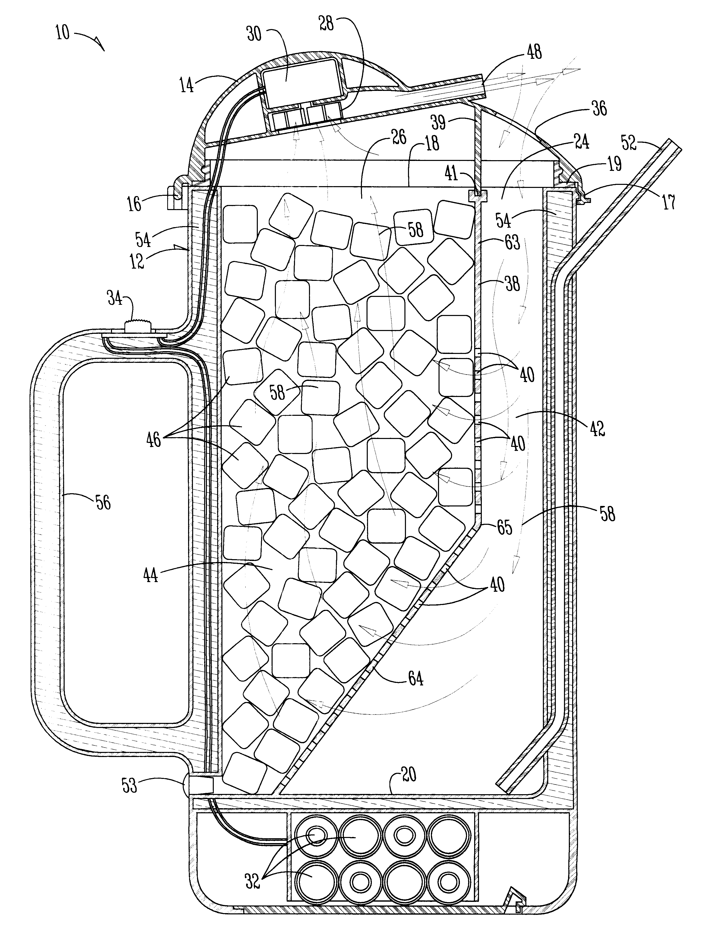
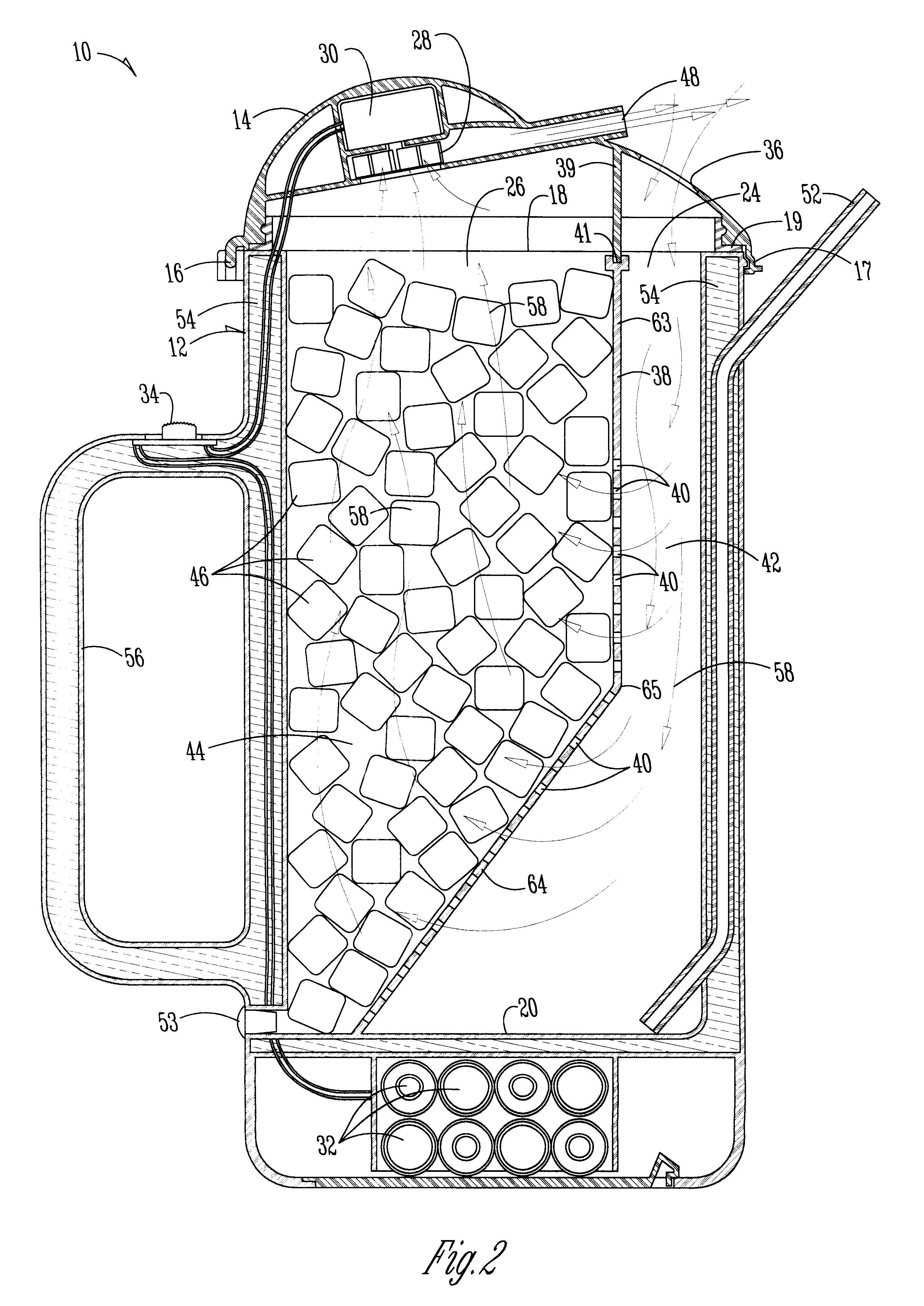
the present invention is shown in FIG. 9. In this embodiment, the portable air conditioner 10C has two compartments 44, 146 containing cold substances. The air flows through one compartment 44 through the vents 142 located at the bottom 144 of the separation wall 140 and out through the cool air vent 48. The bottom 144 of the separation wall 140 could be eliminated as long as some space remained between the separation wall 140 and the bottom of the container to allow air to flow. In this embodiment there is a greater amount of ice 46 which will lead to greater cooling of the air. The control of the air flow 58 is the same as that described for the embodiment shown in FIGS. 1-6.

The embodiment disclosed in FIG. 10 is nearly identical to that disclosed in FIGS. 1-6. The separation wall 38 is part of a removable insert 62. The removable insert 62 makes it easier to clean both the interior of the container 12 and the separation wall 38. This feature is particularly handy for cleaning the...


PUM


Abstract

A portable air conditioner/beverage container includes a container having top and bottom ends, a side wall, an air intake opening, and a cool air outlet. Within the container, there is a separation wall. A first space between the separation wall and the side wall defines an air intake region. The air intake region is in fluid communication with the air intake opening. A second space between the side wall and the separation wall defines a cold substance chamber. A blower is in fluid communication with the cool air outlet. A power supply is coupled to the blower. The blower pulls air in through the air intake opening, down through the air intake region, and around the separation wall. Air flows up through the cold substance chamber, through the cool air outlet, where it is expelled onto a user.

Description

1. Field of the InventionThe present invention relates to a portable air conditioner / beverage container. More particularly, the present invention relates to a device that utilizes a fan to pull ambient air through a container that contains a cold substance and blows the cooled air out onto the user of the present invention.2. Problem in the ArtA portable air-conditioning device is generally disclosed in U.S. Pat. No. 5,062,281. While this device aims to function as an air conditioner, it does not have any means to ensure that air passes through a cooling substance, such as ice, before being expelled onto the operator. A lot of the hot air that enters into this device is also expelled as hot air. Air is not sufficiently cooled before exiting onto a user of the device. A need in the art exists for a portable air conditioner that controls air flow so as to ensure efficient operation of the air conditioner. A portable air conditioner that controls the flow of air to ensure efficient coo...

Claims


Application Information

Patent Timeline
Patent Type & Authority Patents(United States)
IPC IPC(8): A47G19/22F25D3/08F24F5/00F25D3/00
CPCA47G19/2288F24F5/0017F25D3/08F25D2303/081F25D2331/81Y02E60/147Y02E60/14
Inventor GERSTEIN, MARK S.
Owner COOL GUYZ
Why Eureka
Try Eureka