Glass bulb for a cathode ray tube and a method for producing a cathode ray tube

a glass bulb and cathode ray tube technology, applied in the manufacture of electric discharge tubes/lamps, instruments, electrode systems, etc., can solve the problems of difficult to write information for a relatively short time, the information had to be separately given to each product, and the particulars of information had to be changed without changing the mask

Inactive Publication Date: 2001-05-08
ASAHI GLASS CO LTD
View PDF5 Cites 26 Cited by
  • Summary
  • Abstract
  • Description
  • Claims
  • Application Information

AI Technical Summary

Problems solved by technology

However, the conventional techniques using printing or laser masking to write the characters or the code had a problem that all required information had to be separately given to individual products.
For example, in the laser masking method, since laser beams had to be passed through a mask to write information, it was impossible to change the particulars of information without changing the mask.
Accordingly, it was difficult to write information for a relatively short time for a large quantity of glass bulbs conveyed during manufacturing steps.
That is, the conventional techniques are inappropriate as an information means to identify a large number of glass bulbs.
Heretofore, conventional characters or a bar code marked by laser on the outer side surface of glass bulbs by a glass bulb manufacturer are insufficient for a cathode ray tube manufacturer to utilize the information written by the glass bulb manufacturer.
However, there has not been proposed such a technique that characters or the like including a large amount of information which can identify individually glass bulbs are marked on the surface of a glass product such as a glass bulb which is transparent, does not have a flat surface and has a mat-surface-like fine recesses and projections, and the information marked therein can be read by means of a pick-up device.
Accordingly, if a trouble or a defective product takes place in a step of producing, it takes much time to trace the cause, and on the other hand, an appropriate way of resolution has not been proposed.
Further, there is a problem in manufacturing steps for the glass bulb such that, for example, it is difficult to supply products manufactured by the same mold or the same machine in a forming or hot processing step, in the intentionally optimum combination, to the next polishing step at which there are a large number of lines for polishing.
This difficulty is applicable also to cathode ray tube manufacturers.
In short, due to restrictions to an amount of information to be written in and difficulty in writing the characters and so on for glass bulbs, there is a limit in using the characters or codes in manufacturing steps in each of the glass bulb manufacturers and cathode ray tube manufacturers.
Thus, there has not been known a method for producing a glass bulb or a cathode ray tube wherein marked characters or codes can be used commonly for both manufacturers, to make it unnecessary for the cathode ray tube manufacturer to use its own characters or codes.
However, the application of the two-dimensional matrix code, in particular, a two-dimensional matrix code comprised of a plurality of dots, to a glass bulb has not been studied.
Accordingly, when the depth d is less than 5 .mu.m, the diameter L is also less than 50 .mu.m, which causes difficulty in reading correctly the two-dimensional matrix code.
On the other hand, when d and L exceed 100 .mu.m and 400 .mu.m respectively, there will arise problems that the marking by laser becomes difficult and fine cracks are formed around the recess 26.
Further, the formation of a recess having an excessive size will cause strength reduction and the glass bulb is destroyed when a stress of vacuum is applied thereto.
Accordingly, when the two-dimensional matrix code is to be read, light and darkness provided by any dot can not sufficiently be obtained whereby it is difficult to recognize the dot correctly.
As a result, a cathode ray tube using such glass bulb is apt to be broken due to the acute recesses.
When the S / N ratio is smaller than 1.5, the reading of the two-dimensional matrix code becomes difficult.

Method used


Image

  • Glass bulb for a cathode ray tube and a method for producing a cathode ray tube
  • Glass bulb for a cathode ray tube and a method for producing a cathode ray tube
  • Glass bulb for a cathode ray tube and a method for producing a cathode ray tube

Examples


Embodiment Construction

An example of the present invention will be described with reference to the drawings.

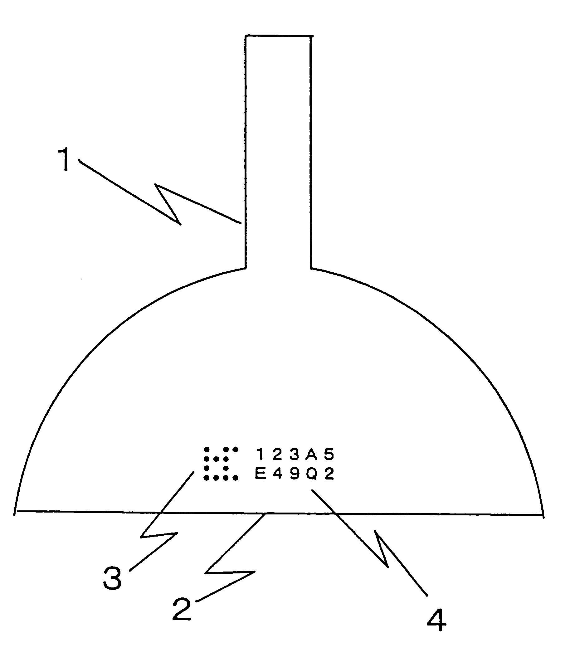
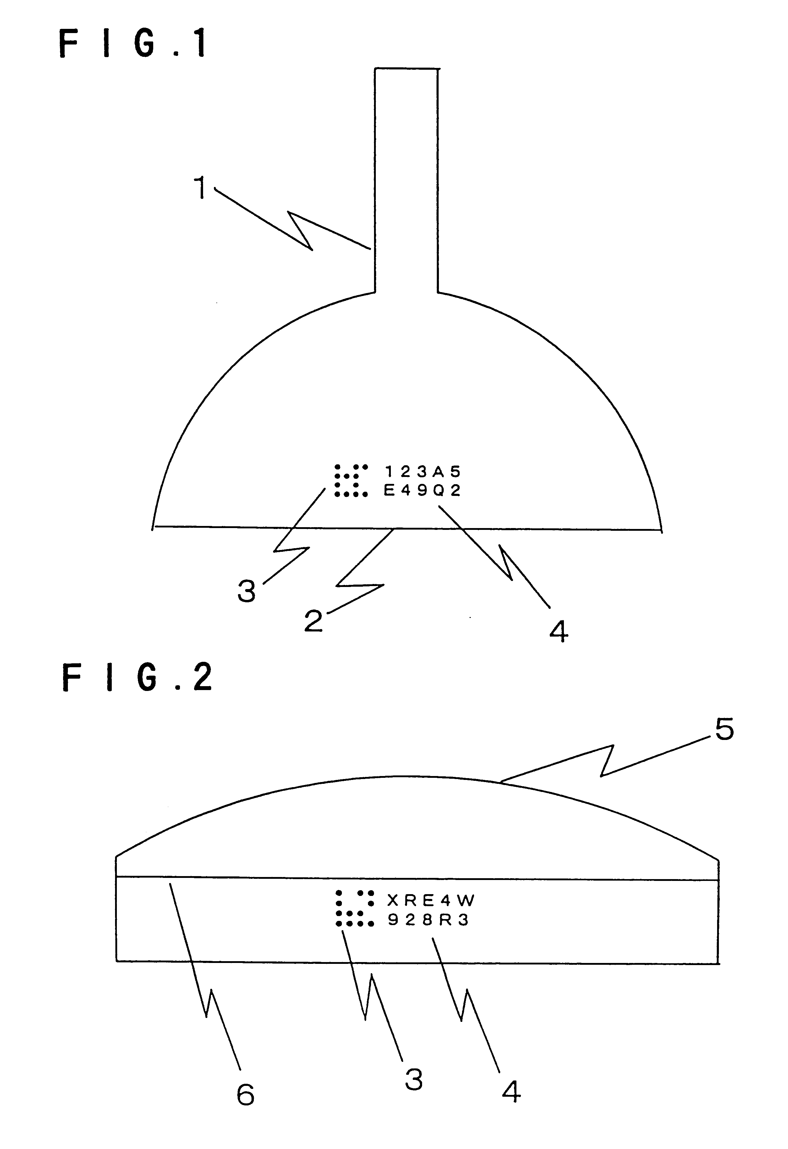
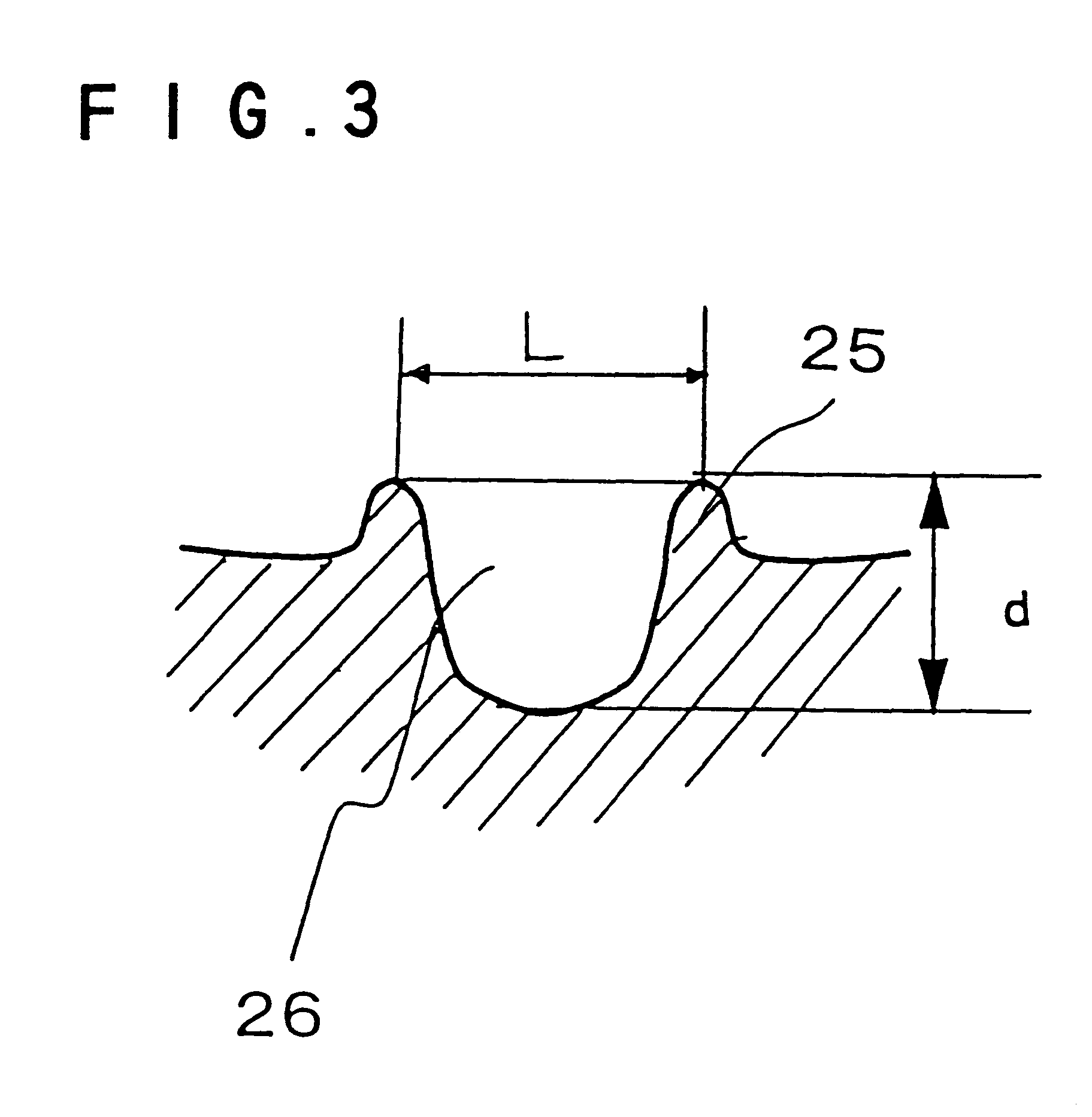
FIG. 1 is a diagram showing a funnel 1 having an outer side surface in which a data matrix type two-dimensional matrix code 3 and characters and figures (hereinbelow, referred to as characters) 4 representing an inherent information on the funnel, which is incorporated in the two-dimensional matrix code are marked by laser at a position 20 mm higher than the edge surface 2 to be sealed and a central portion of a longer side of the funnel. A serial information for identifying the funnel is incorporated in the two-dimensional matrix code comprised of a plurality of dots. The size of the two-dimensional matrix code 3 is 6 mm square, the depth of each dot is about 20 .mu.m and the diameter is about 150 .mu.m.

FIG. 2 is a diagram showing a panel 5 in which a data matrix type two-dimensional matrix code 3 and characters 4 are marked, in the same manner as the funnel 1 in FIG. 1, at a position 30 mm apart f...


PUM

PropertyMeasurementUnit
diameteraaaaaaaaaa
depthaaaaaaaaaa
temperatureaaaaaaaaaa

Abstract

Manufacturing steps for a cathode ray tube or a glass bulb for the cathode ray tube are controlled in such a manner that a two-dimensional matrix code 3 comprised of a plurality of dots is marked by laser in an outer side surface of a glass bulb 1, 5, the two-dimensional matrix code 3 containing the information which can identify individually glass bulbs, and the manufacturing steps are conducted by using a computer and the particulars specified by the serial information.

Description

1. Field of the InventionThe present invention relates to a glass bulb for a cathode ray tube having a two-dimensional matrix code comprised of a plurality of dots in a predetermined portion of an outer side surface of the glass bulb, a method for producing such glass bulb and a method for producing a cathode ray tube using such glass bulb.2. Discussion of the BackgroundThere has been known a technique that information on the glass bulb or information on operating conditions (including information on the particulars of operations) is directly written as marked characters or a code in an outer side surface of a glass bulb for a cathode ray tube (hereinbelow, referred to as a glass bulb), and manufacturing steps for the glass bulb are controlled based on the information read. Generally, the writing of such information in the outer side surface of the glass bulb is conducted by directly printing a heat-resistant material or attaching a heat-resistant label, or marking by sand-blasting ...

Claims


Application Information

Patent Timeline
Patent Type & Authority Patents(United States)
IPC IPC(8): G06K1/00G06K1/12H01J29/86H01J9/20H01J9/42H01J9/00
CPCG06K1/126H01J9/00H01J9/20H01J9/42H01J29/86H01J2209/466C03C23/0025
Inventor SHINODA, MASAYUKI
Owner ASAHI GLASS CO LTD
Why Eureka
Try Eureka