Accessory with internal adjustments controlled by host

a technology of host and adjustment device, applied in the field of accessory, can solve the problems of substantial measurement error, insufficient calibration, compensation or otherwise appropriate configuration, and inability to properly adjust the internal adjustment of the accessory, etc., and achieve the effect of reducing the number of adjustments

Inactive Publication Date: 2001-05-15
TEKTRONIX INC
View PDF24 Cites 55 Cited by
  • Summary
  • Abstract
  • Description
  • Claims
  • Application Information

AI Technical Summary

Benefits of technology

The present invention provides a method and system for connecting an accessory to a host device while accommodating the unique characteristics of the accessory. This allows for the selection of signal bandwidth, the AC/DC coupling of the accessory, total attenuation across the signal path, and the signal level range based on the capabilities of the accessory.

Problems solved by technology

The technical problem addressed in this patent is the complexity and time-consuming process of properly configuring accessories, such as probes, for use with host devices, such as oscilloscopes. This is due to the need to select the correct accessory for the host device and ensure that it is properly calibrated and configured. The patent aims to simplify this process by providing an accessory with internal adjustments controlled by the host.

Method used


Image

  • Accessory with internal adjustments controlled by host
  • Accessory with internal adjustments controlled by host
  • Accessory with internal adjustments controlled by host

Examples


Embodiment Construction

Reference will now be made in detail to the present preferred embodiments of the invention, examples of which are illustrated in the accompanying drawings. Wherever possible, the same reference numbers will be used throughout the drawings to refer to the same or like parts.

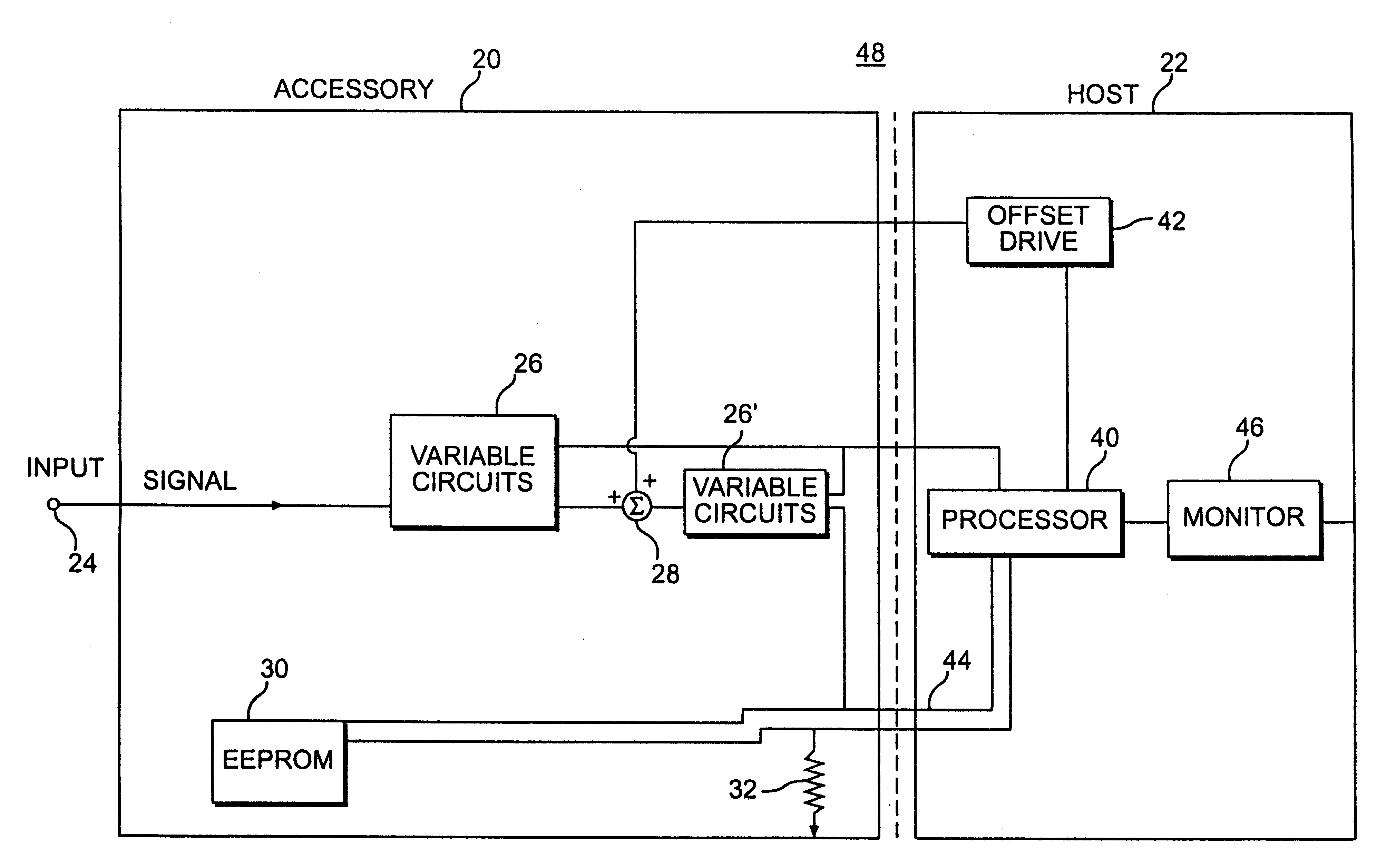
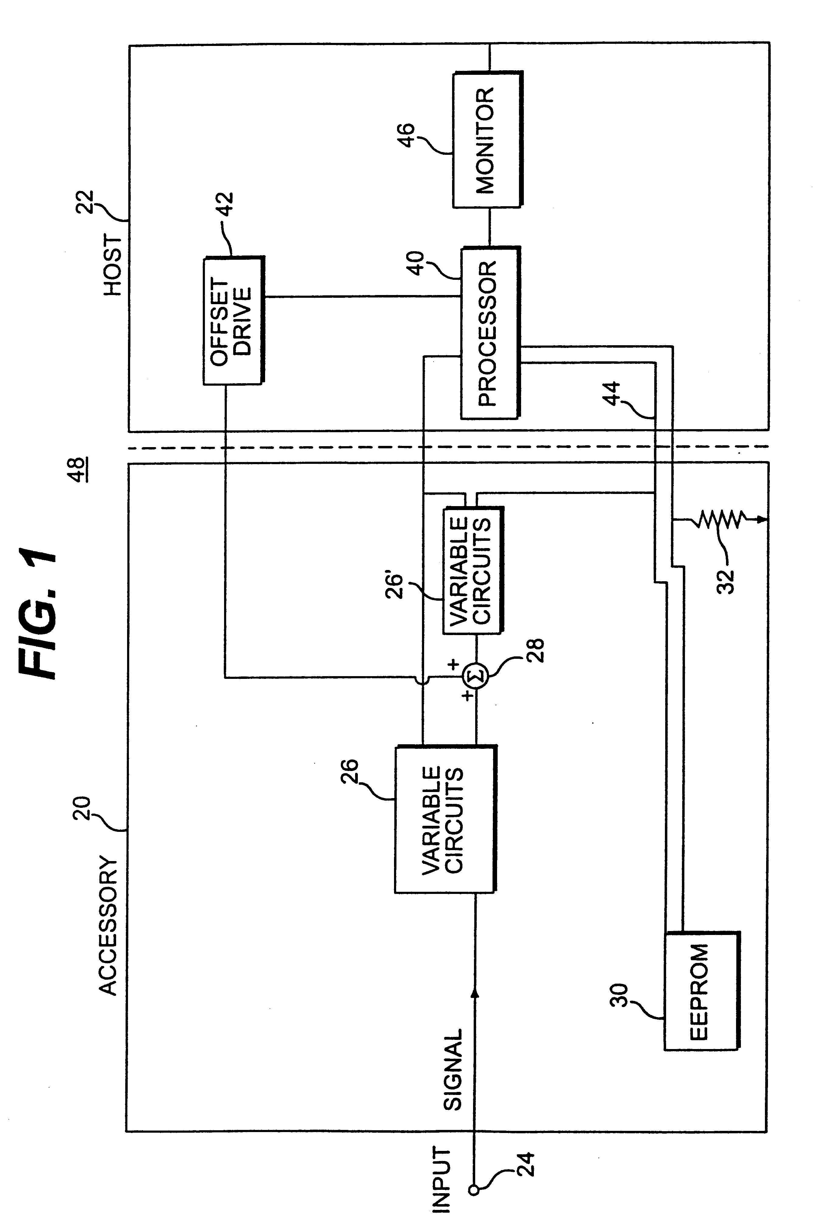
Methods and systems consistent with the present invention may be implemented using an accessory and host model as shown in FIG. 1. FIG. 1 shows an accessory 20 and host 22. Accessory 20 is shown in FIG. 1 as including an input 24, variable circuit: 26, and variable circuit 26', offset injector 28, EEPROM 30, and signaling resistor 32. Host 22 is shown in FIG. 1 as including processor 40, offset drive 42, serial communications interface 44, and monitor 46.

Accessory 20 of FIG. 1 has an input 24 which is connected along a signal path to variable circuits 26. Variable circuits 26 have an output to offset injector 28, which is connected to the input of variable circuits 26'. Variable circuits 26' send output to process...


PUM


Abstract

An electronic accessory assembly to be used with a host electronic instrument provides previously recorded data from a non-volatile memory as to the accessory's operational capabilities. This memory is accessed by a host device either when the host device is powered up, or when an new accessory is connected to the host device. The host device then uses this information along with the operational requirements of the user to set the operational parameters of the accessory/host combination to optimally perform the functions required by the user.

Description


Claims


Application Information

Patent Timeline
Owner TEKTRONIX INC
Why Eureka
Try Eureka