Calender roll system

Inactive Publication Date: 2001-05-22
VOITH SULZER PAPIERTECHN PATENT
View PDF9 Cites 4 Cited by
  • Summary
  • Abstract
  • Description
  • Claims
  • Application Information

AI Technical Summary

Problems solved by technology

However, this is on the precondition that deflection of the rolls is present.
For this kind of off-line calender roll system, a single drive mechanism on a roll that d

Method used


Image

  • Calender roll system
  • Calender roll system
  • Calender roll system

Examples


Example

The particulars shown herein are by way of example and for purposes of illustrative discussion of the embodiments of the present invention only and are presented in the cause of providing what is believed to be the most useful and readily understood description of the principles and conceptual aspects of the present invention. In this regard, no attempt is made to show structural details of the present invention in more detail than is necessary for the fundamental understanding of the present invention, the description taken with the drawings making apparent to those skilled in the art how the several forms of the present invention may be embodied in practice.

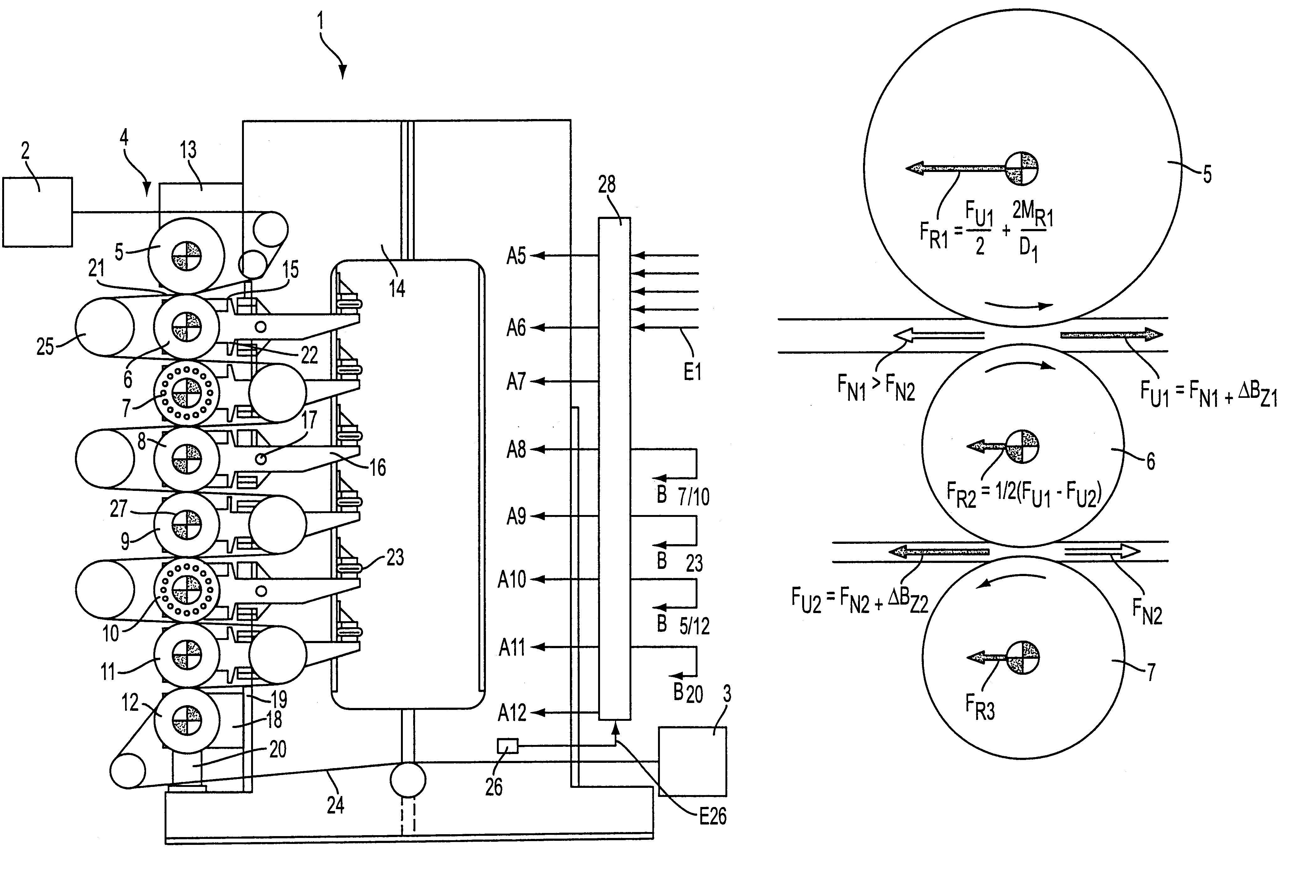
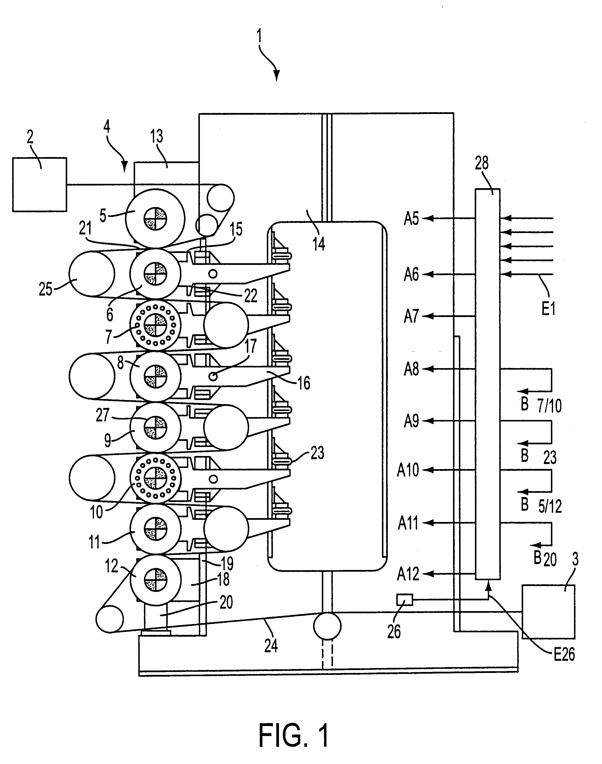
A calender roll system 1, as schematically illustrated in FIG. 1, may be arranged, e.g., as an off-line calender roll system, between a payout station 2 and a winding station 3. However, calender roll system 1 may also be utilized as an in-line calender roll system and arranged to follow an outlet side of a paper-making machine...


PUM


Abstract

A calender roll system and method for operating the same. The calender roll system includes a roll stack having at least one center roll positioned between two end rolls, in which each of the at least one center roll and the two end rolls have a drive mechanism, and in which the rolls can be loaded in a stacking direction. The method includes loading the rolls to form at least one working nip with at least one center roll, and, in the at least one working gap, bending the at least one center roll out of the plane of the roll stack. Reaction forces required to bend the at least one center roll are generated by corresponding adjustment of drive moments of the at least one center roll.

Description

The present application claims priority under 35 U.S.C. .sctn.119 of German Patent Application No. 198 03 323.0, filed on Jan. 29, 1998, the disclosure of which is expressly incorporated by reference herein in its entirety.1. Field of the InventionThe present invention relates to a calender roll system and a method of operating the calender roll system. The calender roll system includes a roll stack having at least one center roll between two end rolls, and a drive mechanism for each of the end and center rolls. The rolls can be loaded in the stacking direction.2. Discussion of Background InformationGerman Patent Disclosure DE 295 18 424 discloses a known calender roll system of the type generally discussed above, in which five and more rolls, preferably eight rolls, are arranged one above the other. The rolls form a number of working nips or gaps, which are defined by one hard roll and one elastic roll, and one varying nip, which is defined by two elastic rolls. Each roll is provid...

Claims


Application Information

Patent Timeline
IPC IPC(8): D21G1/00
CPCD21G1/00D21G1/0006D21G1/0033
Inventor KAYSER, FRANZ
Owner VOITH SULZER PAPIERTECHN PATENT
Why Eureka
Try Eureka