Intersomatic setting and fusion system

Inactive Publication Date: 2001-05-22
SCIENTX
View PDF6 Cites 711 Cited by
  • Summary
  • Abstract
  • Description
  • Claims
  • Application Information

AI Technical Summary

Benefits of technology

an external plate extending in a plane substantially perpendicular to the insertion plane of the cage, on either side thereof, and having an anchor device adapted for anchoring at least to the two adjacent vertebrae that is to be secured together by the cage.

Problems solved by technology

Such a prosthesis has a drawback concerning the anchor screws which are subjected to large forces that can cause the screws to become at least partially disconnected from the vertebrae, and thus allowing the cage to be relatively mobile.

Method used


Image

  • Intersomatic setting and fusion system
  • Intersomatic setting and fusion system
  • Intersomatic setting and fusion system

Examples


Embodiment Construction

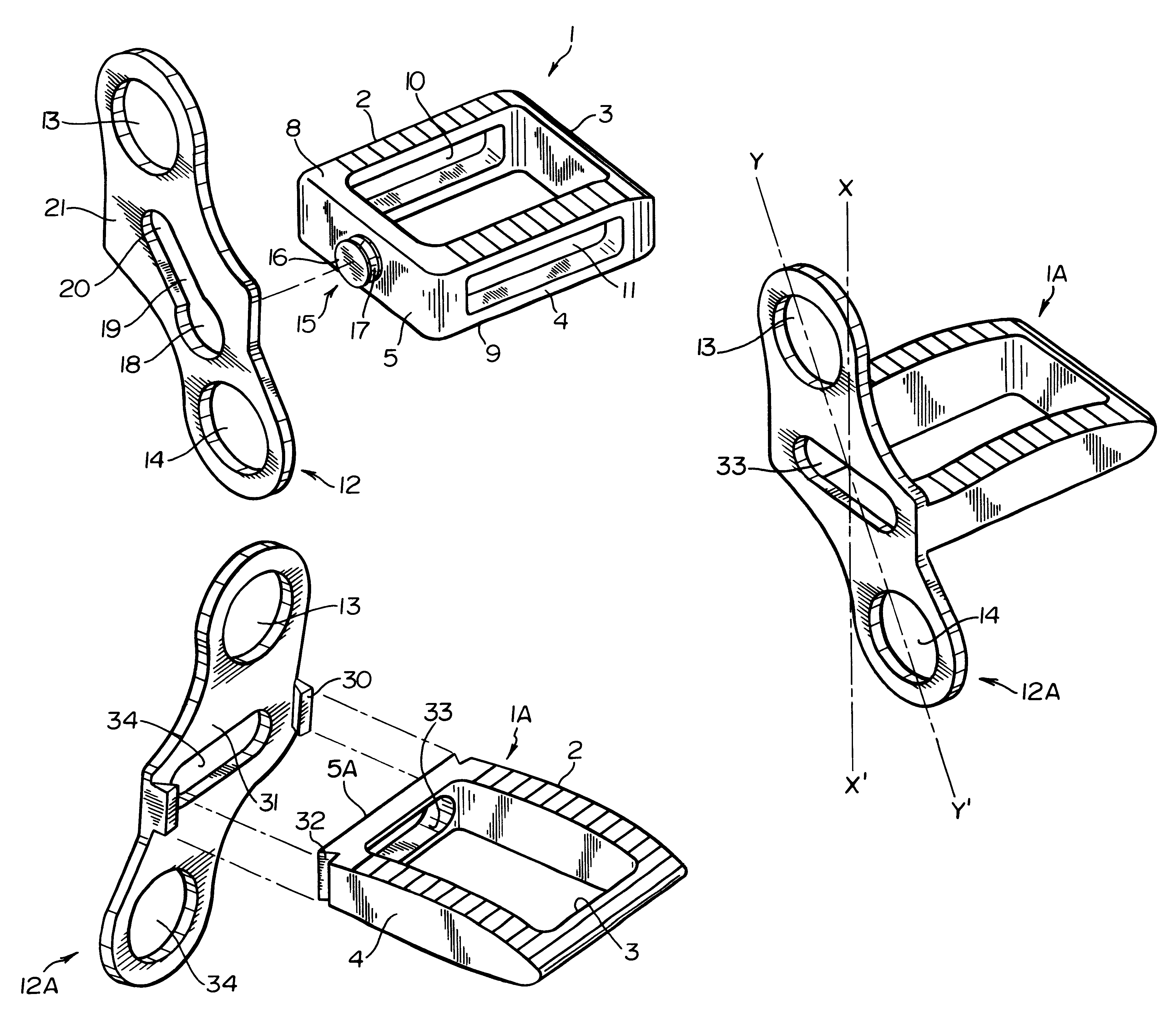
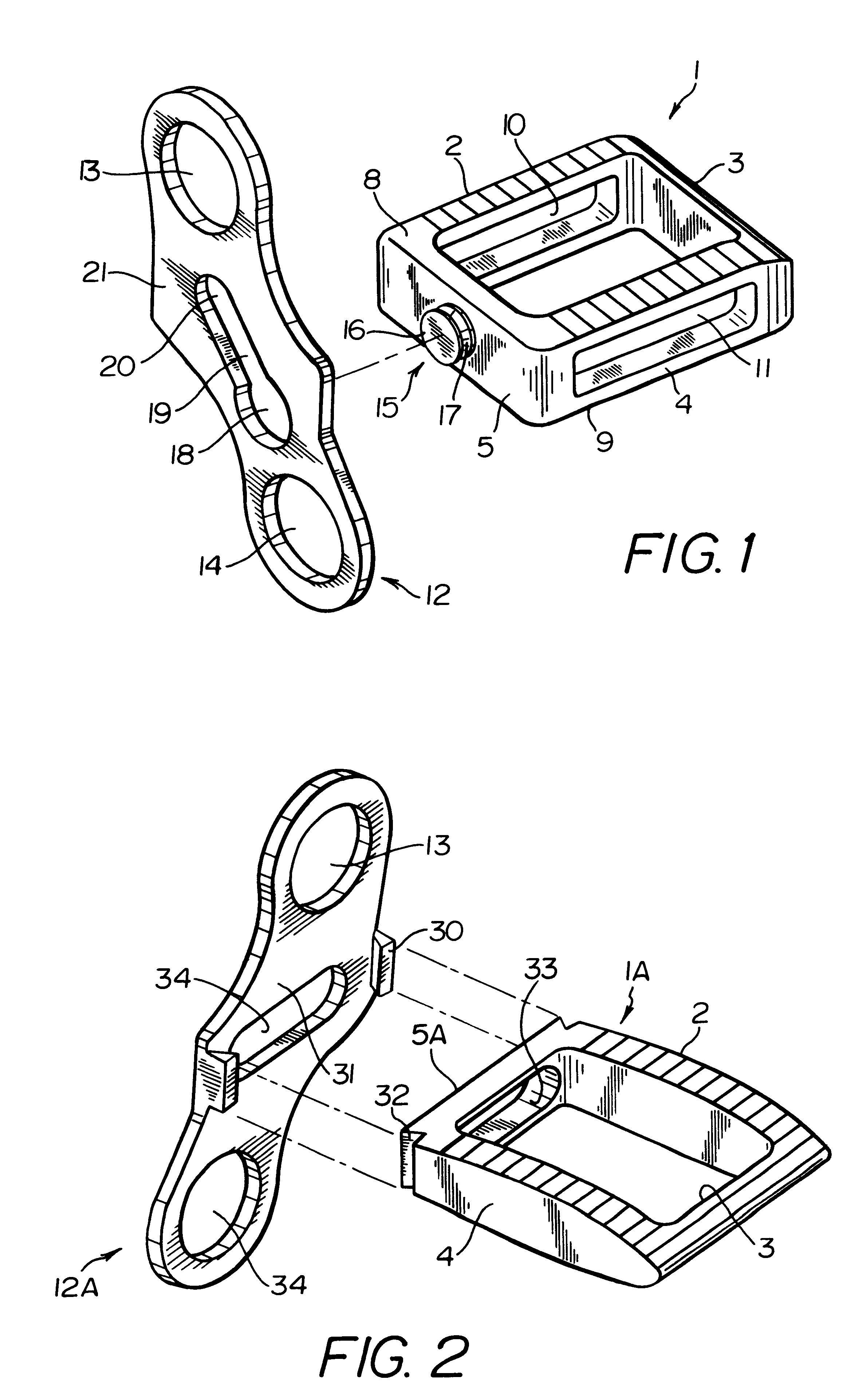
The anterior or front face 5 and posterior face 3 are of heights that are determined so as to conserve an appropriate intervertebral space.

Still in the present example, the side walls 2 and 4 of the cage 1 are provided with large slots 10 and 11 of shape similar to the shapes of the corresponding side walls 2 and 4 through which they pass.

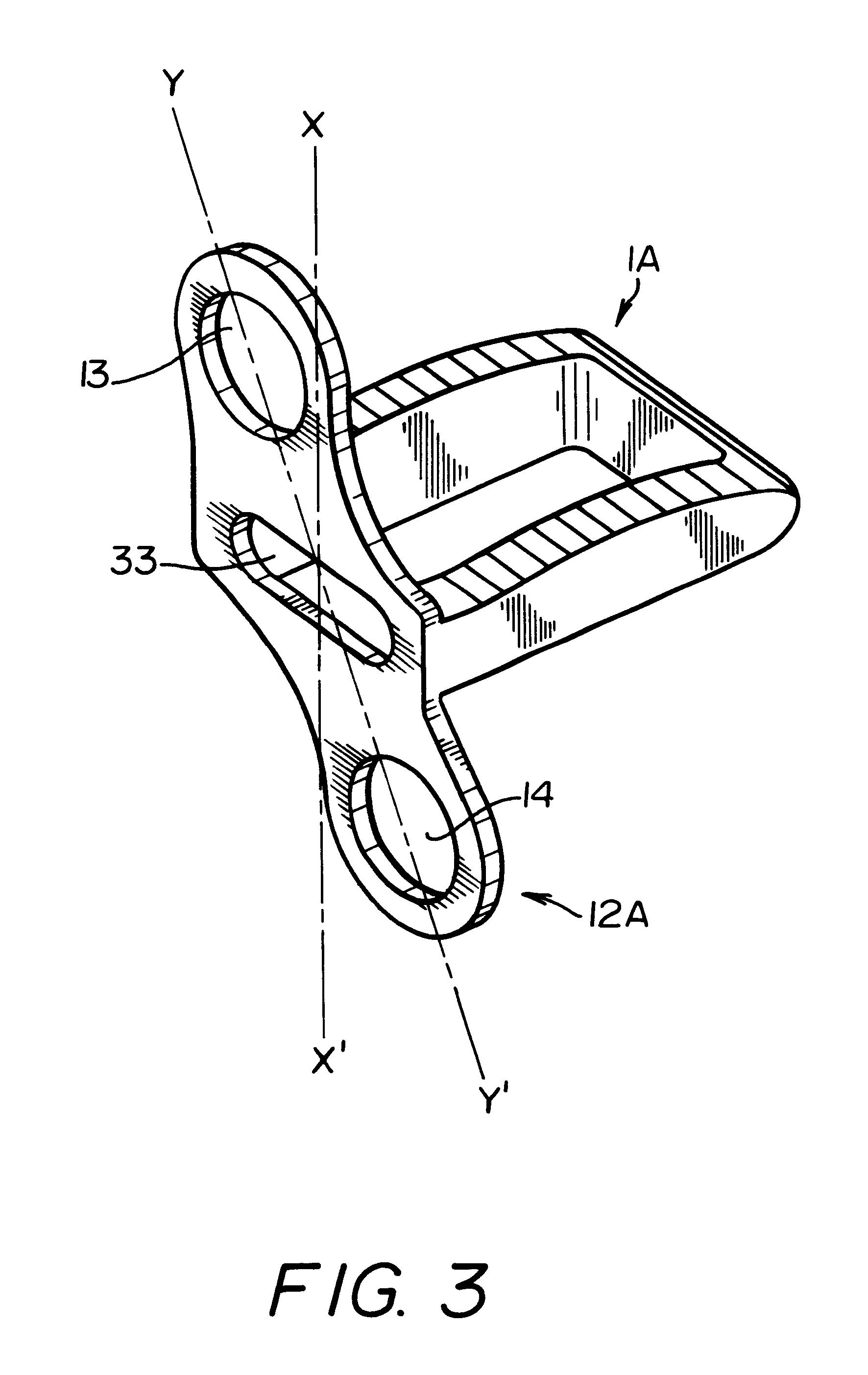
The cage 1 is provided with openings through four of its faces. The cage 1 also carries on its anterior or front face 5 an external strap-forming element, external strap or plate 12 (referred below to as a "plate") extending in a plane that is substantially perpendicular to the insertion plane of the cage 1, on either side thereof, and having at each of its ends anchor devices or fixing holes 13 and 14 for anchoring to at least two adjacent vertebrae in order to connect them together via the cage 1.

Naturally, the external strap or plate 12 could be integrally formed with the internal cage 1, e.g. by molding or casting the cage-and-plate unit.

Nevert...


PUM


Abstract

A system for intersomatic fusion and setting of vertebrae. The system includes at least one open internal cage arranged for receiving spongy bone or bone substitute and is designed to be interposed between two vertebrae during diskectomy. The cage (1) includes on its anterior face (5) an external element forming a plate (12) extending in a plane substantially perpendicular to the insertion plane of the cage (1), and has at each of its ends an anchor device (13,14) adapted for anchoring to at least two adjacent vertebrae to be secured to each other by the cage (1). The system can be separated into two parts, the cage and the plate.

Description

BACKGROUND OF THE INVENTION1. Field of the InventionThe present invention relates to an intersomatic fusion and setting system for vertebrae. The system includes at least one open internal cage receiving spongy bone and designed to be interposed between two vertebrae during diskectomy and the system is capable of installing a bone graft or material encouraging intersomatic fusion, thereby encouraging fusion between the two vertebrae concerned.2. Description of Related ArtSimilar cages are known, for example, from the following patent applications: FR 2 703 580; EP 493 698; EP 599 419; FR 2 124 815; EP 307 241; EP 615 428.These cages are generally ovoid or parallelepipedal in shape. They are rigid, made of metal or of a biocompatible material, and designed to receive spongy bone via open top and bottom faces.Although cages of the above type generally give good results, it is nevertheless true that in some cases it is necessary to position the cage and to ensure that it cannot move so...

Claims


Application Information

Patent Timeline
Patent Type & Authority Patents(United States)
IPC IPC(8): A61F2/44A61B17/70A61F2/28A61F2/00A61F2/30
CPCA61F2/4455A61F2/447A61B17/7059A61F2/442A61F2002/2835A61F2002/30271A61F2002/30387A61F2002/30431A61F2002/30576A61F2002/30578A61F2002/30604A61F2002/30777A61F2002/4475A61F2002/449A61F2220/0025A61F2230/0082A61F2310/00023A61F2002/30261A61F2002/30593
Inventor BENEZECH, JACQUESALBY, ALBERT
Owner SCIENTX
Why Eureka
Try Eureka