

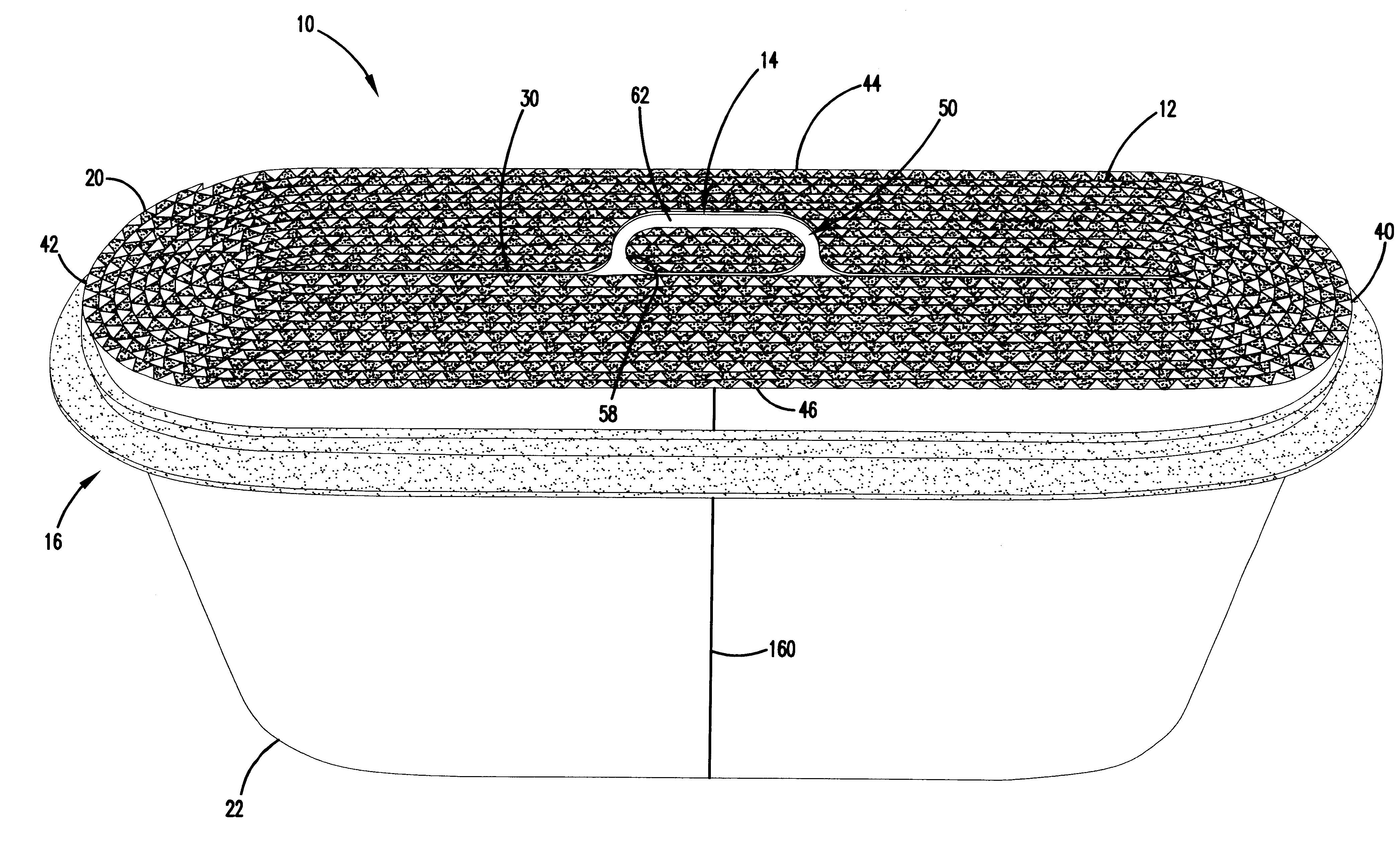
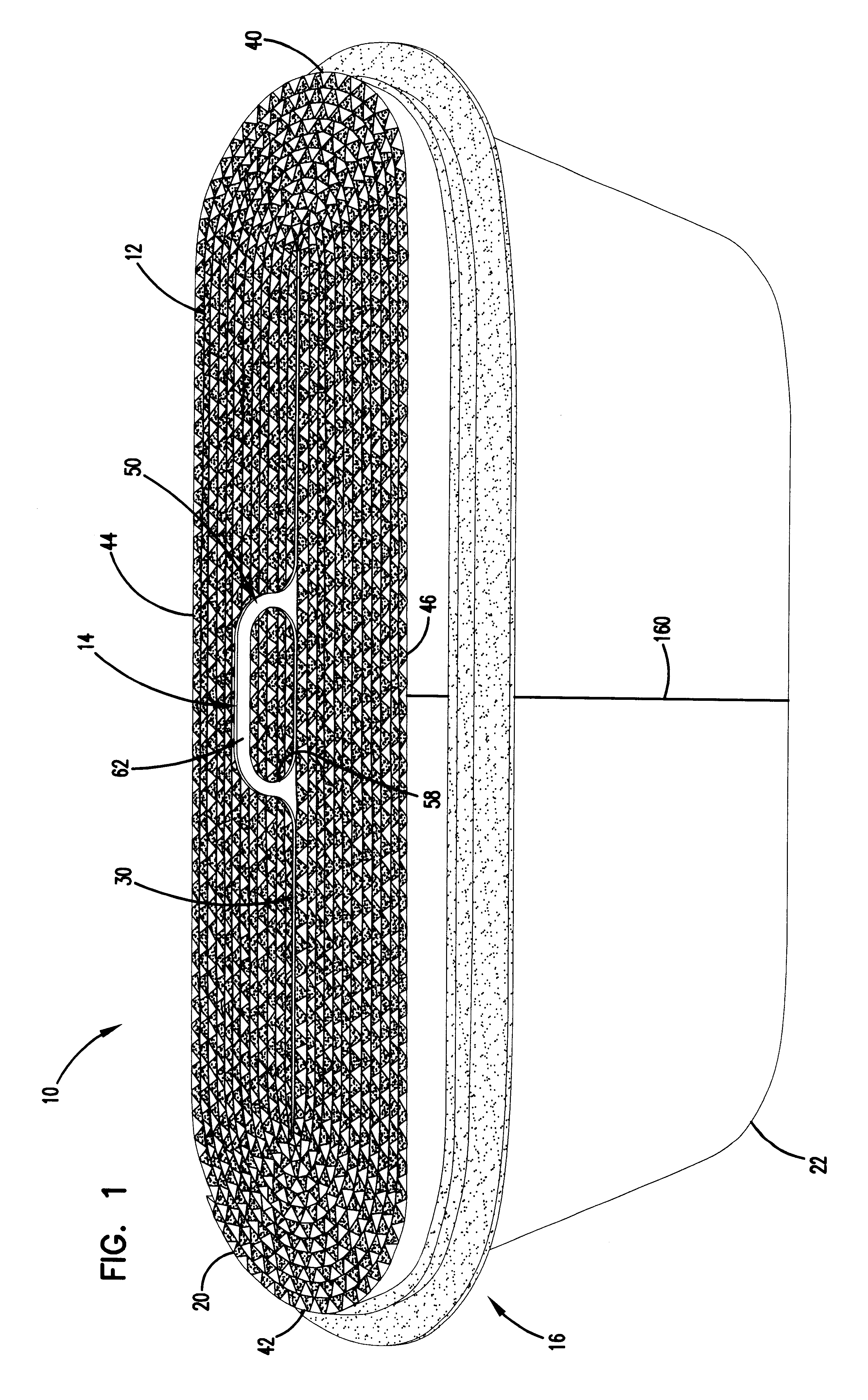
Filter element incorporating a handle member
a filter element and handle technology, applied in the field of filter arrangement, can solve problems such as damage to whatever system, and achieve the effect of reducing the amount of turbulence and convenient manipulation and handling
- Summary
- Abstract
- Description
- Claims
- Application Information
AI Technical Summary
Benefits of technology
Problems solved by technology
Method used
Image

Examples
Embodiment Construction
The following section provides certain example materials that are usable in the arrangements and constructions described herein. Other materials are usable.
The filter media 12 can be cellulose media with the following properties: a basis weight of about 52 lbs. / 3000 ft.sup.2 (84.7 g / m.sup.2); a thickness of about 0.010 in. (0.25 mm); frazier permeability of about 22 ft / min (6.7 m / min); pore size of about 62 microns; wet tensile strength of about 8.5 lbs. / in (3.9 kg / in); burst strength wet off of the machine of about 23 psi (159 kPa). The cellulose media can be treated with fine fiber, for example, fibers having a size (diameter) of 5 microns or less, and in some instances, submicron. A variety of methods can be utilized for application of the fine fiber to the media. Some such approaches are characterized, for example, in U.S. Pat. No. 5,423,892, column 32, at lines 48-60. More specifically, such methods are described in U.S. Pat. Nos. 3,878,014; 3,676,242; 3,841,953; and 3,849,241,...
PUM
| Property | Measurement | Unit |
|---|---|---|
| diameter | aaaaa | aaaaa |
| density | aaaaa | aaaaa |
| width | aaaaa | aaaaa |
Abstract
Description
Claims
Application Information