
Casing for a hot box or blocked brake detection scanner

Inactive Publication Date: 2001-06-05
VAE AG
View PDF10 Cites 16 Cited by
  • Summary
  • Abstract
  • Description
  • Claims
  • Application Information

AI Technical Summary

Benefits of technology

The invention aims at providing a casing of the initially defined kind, which is suitable for being incorporated in a trough-shaped sleeper which safely utilizes the advantages of an installation directly in the trough-shaped sleeper even in adverse meteorological conditions and, in particular, when intensive snow fall or the like is likely to build up a thick layer of snow or ice on the detector. To solve this problem, the configuration according to the invention essentially consists in the casing being comprised of a casing lower part and a lid, the lid being designed as a chimney top with lateral surfaces converging towards the upper thereof and carrying an electrical heating means on their inner sides. The lid includes openings for the scanning beams of one or more infrared detectors on its upper edge or near its upper edge. By providing, in addition to a casing lower part which, in accordance with a preferred further development of the invention, is formed by the trough-shaped sleeper itself and a lid which is designed as a chimney top having lateral surfaces converging towards the upper edge, it is ensured that even in case of heavy snow fall, the snow will descend along the converging lateral surfaces under the action of gravity. By providing electrical heating means on the inner sides of the lateral surfaces and openings for the scanning beams of the infrared detector in the lid on its upper edge or near its upper edge, it is ensured that the integrated heating reliably keeps clear from snow or ice the respective opening cross section on the upper side of the lid by ascending hot air so as to allow the safe scanning and detection of hot boxes or blocked brakes. The surface available for a possible snow cover is relatively small, since that surface directly merges into the laterally sloping lateral surfaces converging towards the upper edge. By heating those lateral surfaces, at least a film of snow in direct contact with the lateral walls will melt such that the snow load can descend under its own weight and melt subsequently. Due to a stacking effect, the openings on the upper edge are safely kept clear even at a comparatively low heating performance, since, bearing in mind the small upper surface, the overall amount of snow or ice built up thereabove remains relatively small. This applies all the more, since the upper edge of the casing lid is brought near the travelling edges of the rail due to the chimney top such that even the relative wind of rolling rail vehicles will cause an additional mechanical cleaning effect. Advantageously, the configuration is devised such that the casing lower part comprises a further electrical heating means and is provided with discharge openings for melt water so as to prevent major amounts of snow from collecting in the interior of the upwardly open casing.
In a particularly simple manner, the heating means of the lid is designed as an electrical resistance heater having windings which extend substantially parallel with the bottom of the casing lower part. Such an arrangement of the electrical resistance heater directly results in the desired flow course of the ascending hot air, thus ensuring particularly efficient clearing of snow even at low heating performances.

Problems solved by technology

With such a large distance, larger amounts of snow or ice may build up above the detector, thus impairing or even preventing measurements.

Method used


Image

  • Casing for a hot box or blocked brake detection scanner
  • Casing for a hot box or blocked brake detection scanner
  • Casing for a hot box or blocked brake detection scanner

Examples


Embodiment Construction

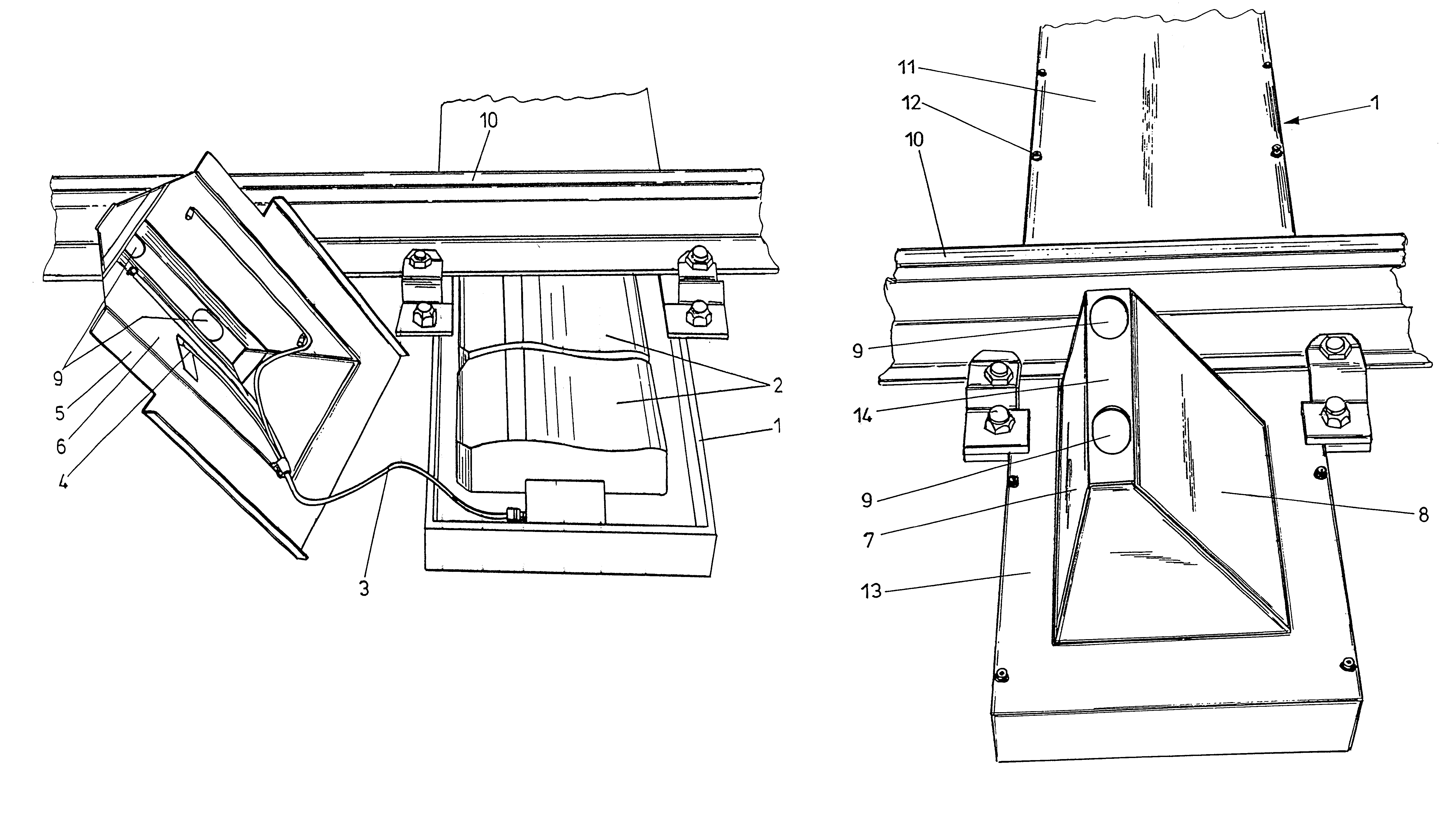
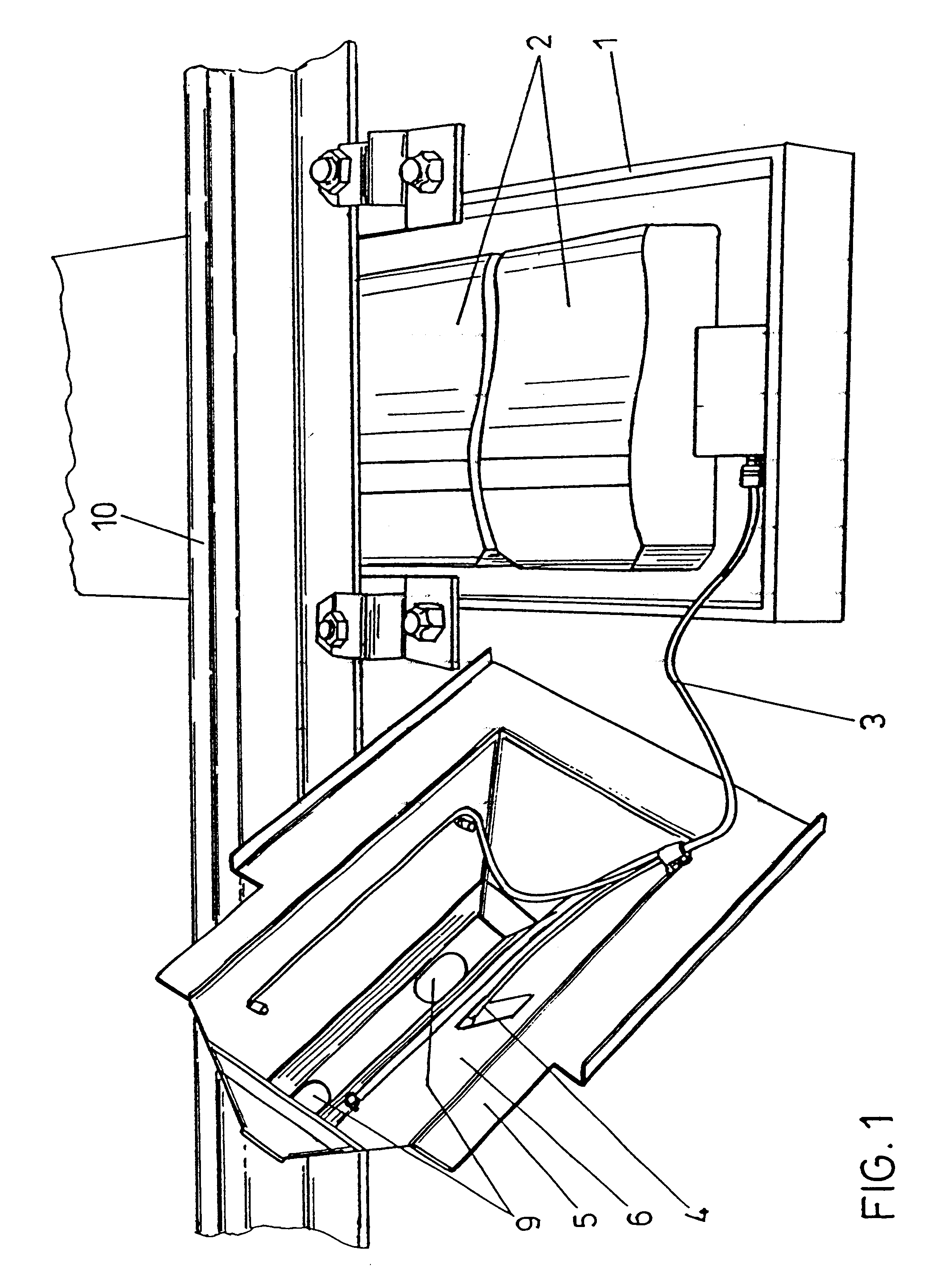
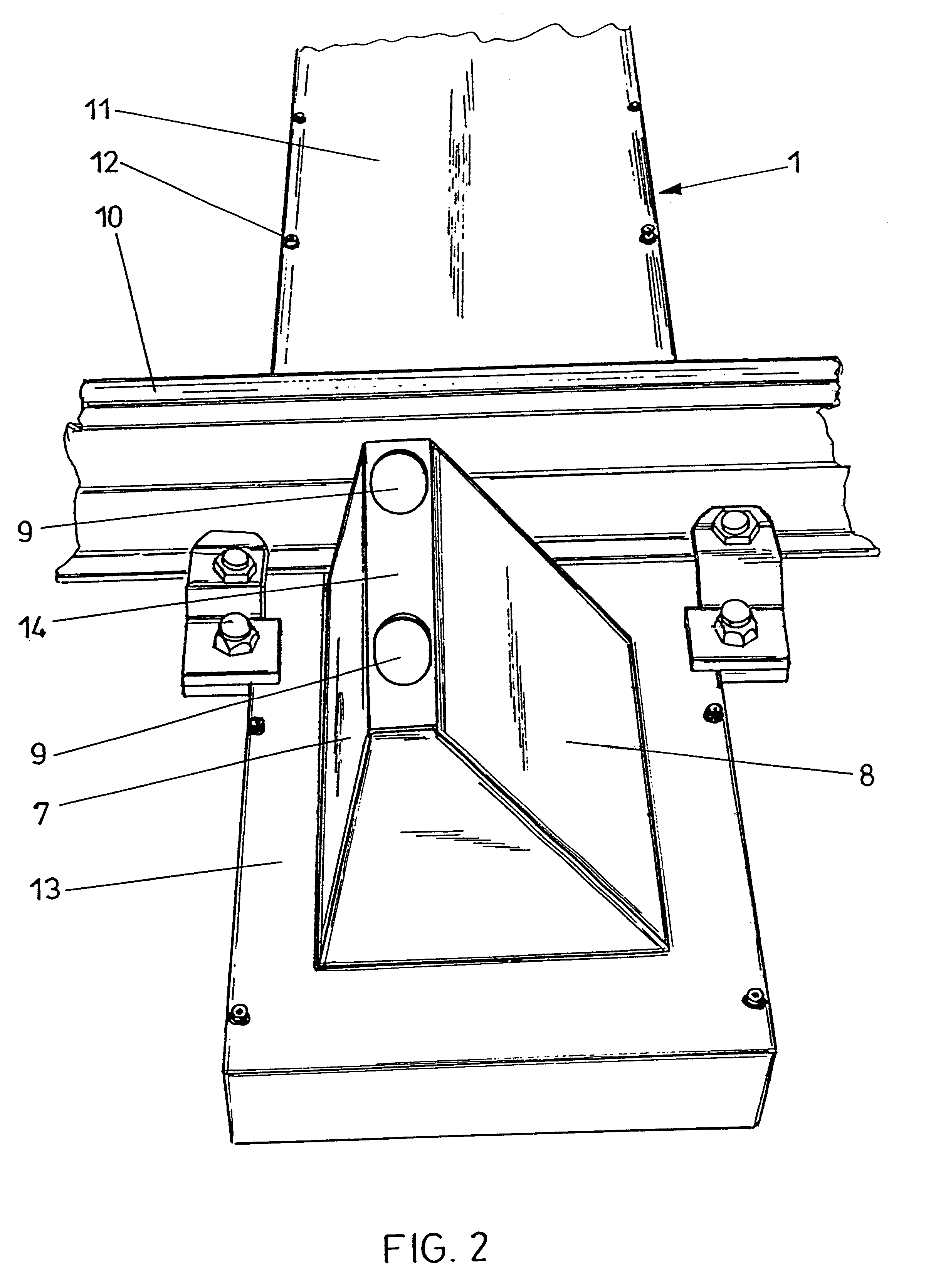
From FIG. 1 a trough-shaped sleeper 1 is apparent, in which hot box detection scanners 2 are inserted. A heating means 4 is provided within the lid of the trough-shaped sleeper, a connecting cable 3 for the heating means 4 being visible in the lid 5. The heating means 4 provided in the lid is designed as a resistance heater which extends over the inner sides 6 of the lid side walls as denoted by 7 and 8 in FIG. 2. As is apparent, in particular, from FIG. 2, the upper edge of the lid includes openings 9 so that the required scanning geometry of the scanner on the bearings of a rolling rail vehicle can be ensured. In FIGS. 1 and 2, the rail is denoted by 10, wherein just one rail is depicted in each case. The trough-shaped sleeper 1 extends over the total width of the track. As is apparent from FIG. 2, the trough-shaped sleeper is closed by a plane lid 11 by means of screws 12. On the laterally protruding parts of the trough-shaped sleeper, in which the hot box detection means 2 is ar...


PUM


Abstract

The invention relates to a casing for a hot box or blocked brake detection scanner (2) comprising infrared detectors and a heating means, wherein the casing is comprised of a casing lower part and a lid (5), the lid (5) is designed as a chimney top with lateral surfaces (7, 8) converging towards the upper edge and carrying an electrical heating means (4) on their inner sides (6), and the lid (5) includes openings (9) for the scanning geometry of the infrared detector(s) on its upper edge or near its upper edge.

Description

1. Field of the InventionThe invention relates to a casing which includes a heating means for a hot box or blocked brake detection scanner comprising infrared detectors. The casing is attached to a track section.2. Prior ArtHot box or blocked brake detection scanners usually are mounted to rails with the measuring openings of the detectors being at a relatively slight distance relative to the rail upper edge. Such a slight distance in case of a snow or ice covering, as a rule, will not constitute a major problem if the layer of snow above the detector is melted by a heating means incorporated in the scanning means. Due to the slight distance, the upper edges of such detectors are cleaned by the relative wind produced by rolling rail vehicles. Known such devices have been described in DE-A-19 18 317, wherein a special supporting structure is screwed to the rail webs and the respective hot box or blocked brake detection means is mounted to the supporting structure.DE-A-42 17 681 has a...

Claims


Application Information

Patent Timeline
IPC IPC(8): B61K9/00B61K9/06B61K9/04
CPCB61K9/06
Inventor STEURER, ERWINNAYER, WOLFGANG
Owner VAE AG
Learn More