Angularly adjustable coupling
- Summary
- Abstract
- Description
- Claims
- Application Information
AI Technical Summary
Benefits of technology
Problems solved by technology
Method used
Image

Examples
first embodiment
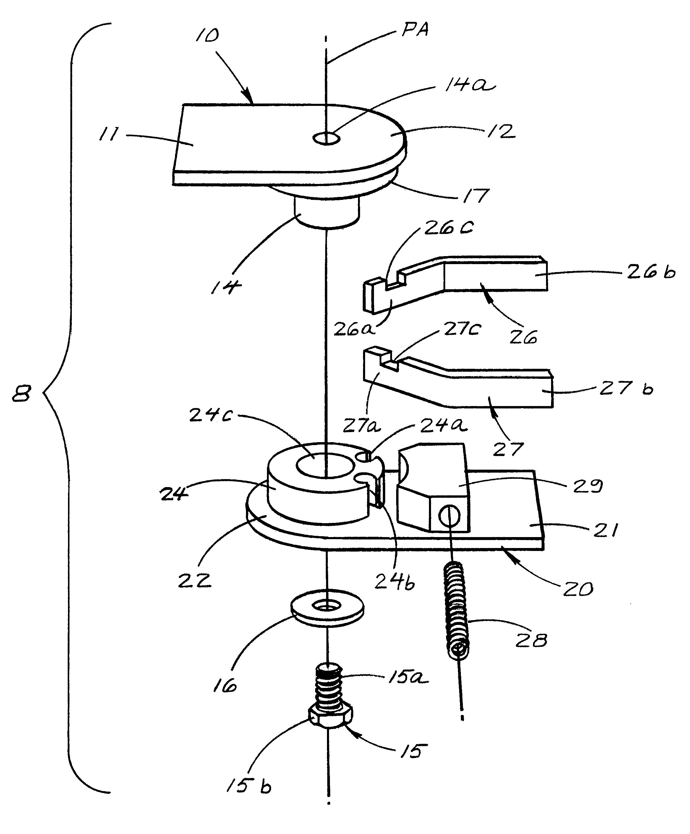
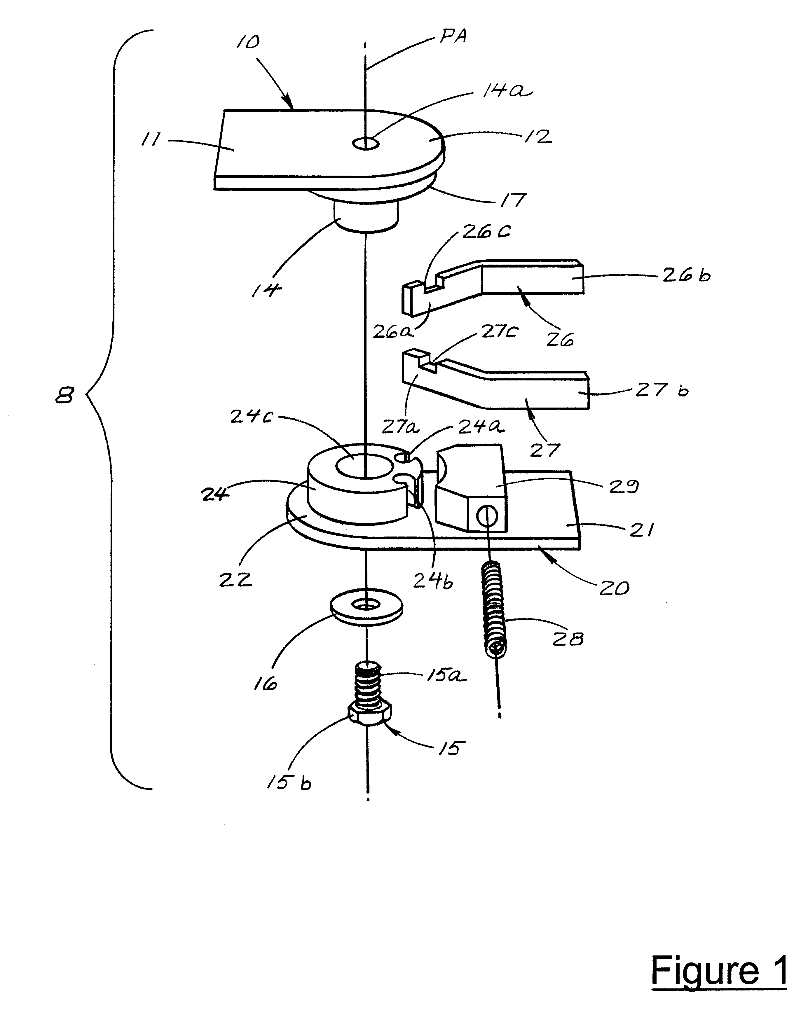
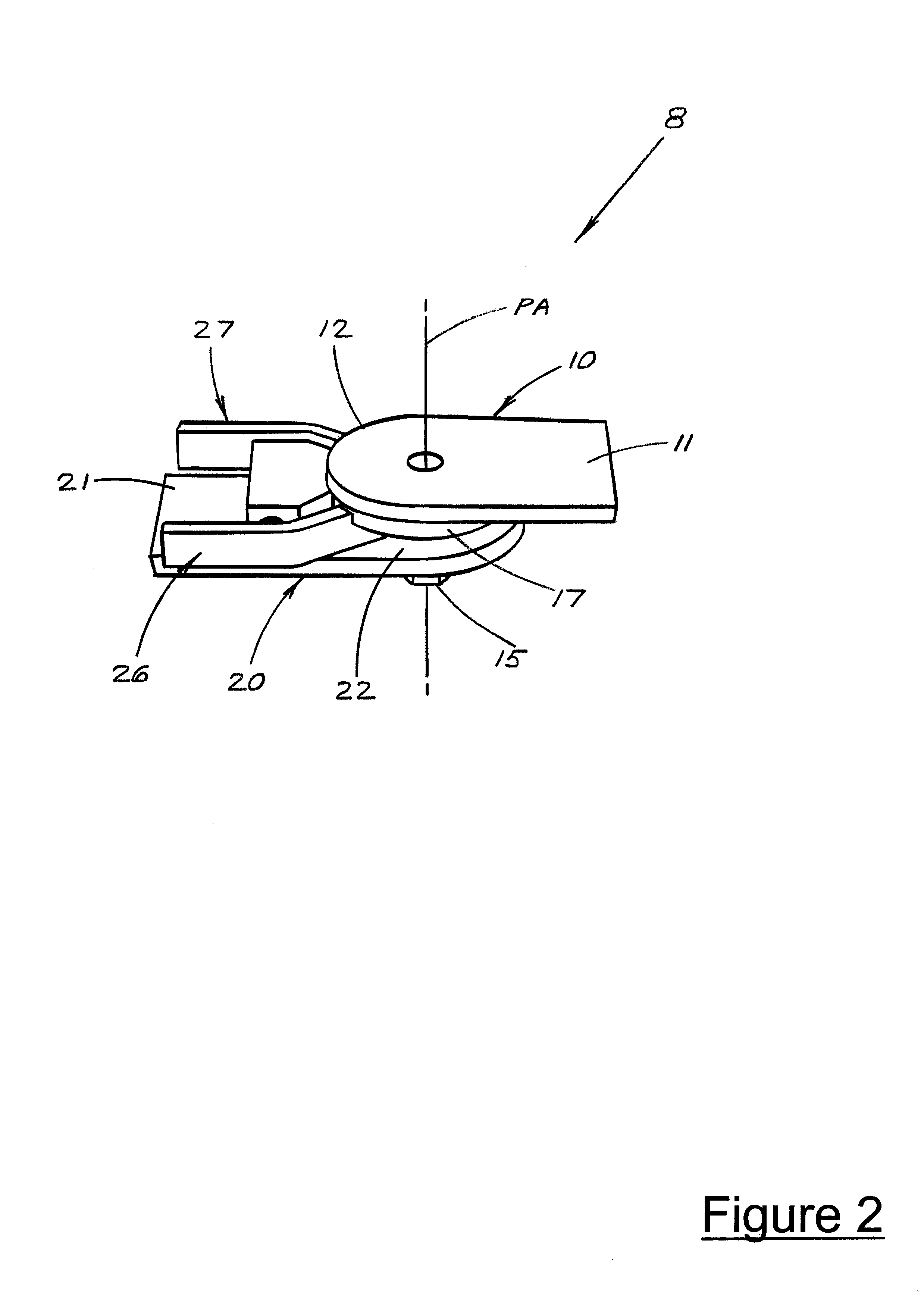
Referring to FIGS. 1 and 2 an angularly adjustable coupling is generally shown at 8. The angularly adjustable coupling 8 includes a first coupling member, generally designated 10, and a second coupling member, generally designated 20. The two coupling members are pivotally coupled together about a pivot axis PA in a manner which allows the user to conveniently adjust their angular positions and to securely lock them in the newly-adjusted position.
Coupling member 10 includes an outer section 11 for attaching one of the devices (not shown) to be coupled, and an inner section 12 for pivotally mounting such a device to coupling member 20 for coupling the other device (not shown) to be coupled. As will be clear to those of skill in the art, the outer section 11 may be formed in any of several configurations for attaching to a device to be coupled to a second device. For example, the outer section 11 could be formed with a circular bore to accept a threaded shaft or may be formed with a p...
second embodiment
Referring now to FIGS. 3 and 4, an angularly adjustable coupling according to the present invention is generally shown at 40. This embodiment differs from the previous embodiment mainly in that it includes four pivotal arms rather than two pivotal arms to increase the locking force exerted between the two coupling members. This embodiment also differs somewhat in the configuration of the two coupling members. However, as will be clear to those of skill in the art, the coupling members in any embodiment may be reconfigured in various ways without departing from the teachings of the present invention.
The angularly adjustable coupling 40 includes a first coupling member 42 which takes the form of a circular disk 44 with a boss 46 extending perpendicularly downwardly from the center thereof. The first coupling member 42 also has a locking rib 48 extending perpendicularly downwardly from the perimeter of the disk 44. The disk 44, boss 46, and rib 48 are all coaxial about the central pivo...
third embodiment
Referring now to FIGS. 5 and 6, an angularly adjustable coupling according to the present invention is generally shown at 80. This embodiment differs from the previous embodiments in several respects. First, this embodiment uses six pivotal arms arranged radially around the coupling so as to give a uniform and substantial interlock. Also, the pivotal arms are moved from their locked to their unlocked position by a push pad with pins that force the pivotal arms into a neutral or unlocked position. This embodiment of the coupling 80 includes a first coupling member 82 and a second coupling member 84 which nest together and may be selectively locked to prevent relative angular rotation, and released to allow relative angular rotation. The first coupling member 82 is similar to the first coupling member 42 in the previous embodiment but differs in that its a two piece design. Obviously, either embodiment may be made to use either a one piece or two piece first coupling member. The first...
PUM
 Abstract
Description
Claims
Application Information
 - R&D
- Intellectual Property
- Life Sciences
- Materials
- Tech Scout
- Unparalleled Data Quality
- Higher Quality Content
- 60% Fewer Hallucinations
Browse by: Latest US Patents, China's latest patents, Technical Efficacy Thesaurus, Application Domain, Technology Topic, Popular Technical Reports.
© 2025 PatSnap. All rights reserved.Legal|Privacy policy|Modern Slavery Act Transparency Statement|Sitemap|About US| Contact US: help@patsnap.com