Secure cluster box unit for mail and parcels

a cluster box and mail technology, applied in the field of door protection, can solve the problems of easy to take a prybar, mail stations are only subject to environmental attacks, and it is not easy to tamper with mail left in such mail boxes

Inactive Publication Date: 2001-06-19
CANAM MARKETING
View PDF26 Cites 68 Cited by
  • Summary
  • Abstract
  • Description
  • Claims
  • Application Information

AI Technical Summary

Benefits of technology

It is an object of the present invention to provide a more secure central box unit for central mail stations.

Problems solved by technology

Recently, tampering with mail left in such mail boxes has become a problem such that the mail must be secured under lock and key.
However, such postal regulations may presume that the mail stations are subject only to environmental attack, such as by wind or rain.
Unfortunately, it is not difficult to take a prybar, such as a crowbar or the like, and force it in between the seam present between the two double doors.
Checks and other financial instruments may be stolen and fraudulently converted into cash, providing the incentive to break and enter into other central post box stations or even the same one on an intermittent or regular basis.
Further investigation indicates that the central sliding linkage may be subject to attack, as the main access door to the linkage may be forced open by bending the main access door's bolt to force the main access door open.
By providing the flange mailbox slot door, attack upon the lock, as by a slide hammer or the like, does not allow the thief or perpetrator to open the mailbox slot door.

Method used


Image

  • Secure cluster box unit for mail and parcels
  • Secure cluster box unit for mail and parcels
  • Secure cluster box unit for mail and parcels

Examples


Embodiment Construction

)

The detailed description set forth below in connection with the appended drawings is intended as a description of presently preferred embodiments of the invention and is not intended to represent the only forms in which the present invention may be constructed and / or utilized. The description sets forth the functions and the sequence of steps for constructing and operating the invention in connection with the illustrated embodiments. However, it is to be understood that the same or equivalent functions and sequences may be accomplished by different embodiments that are also intended to be encompassed within the spirit and scope of the invention.

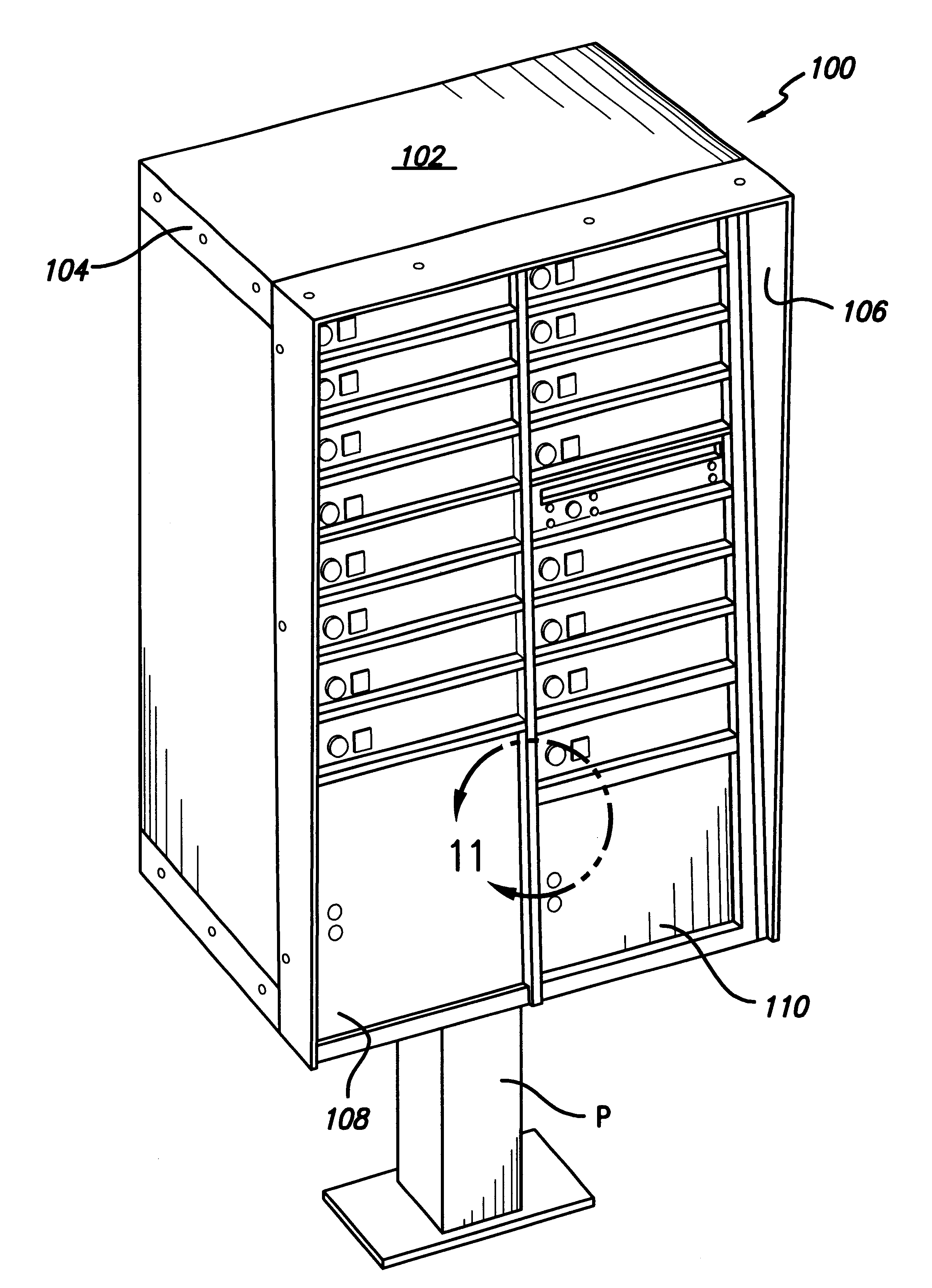
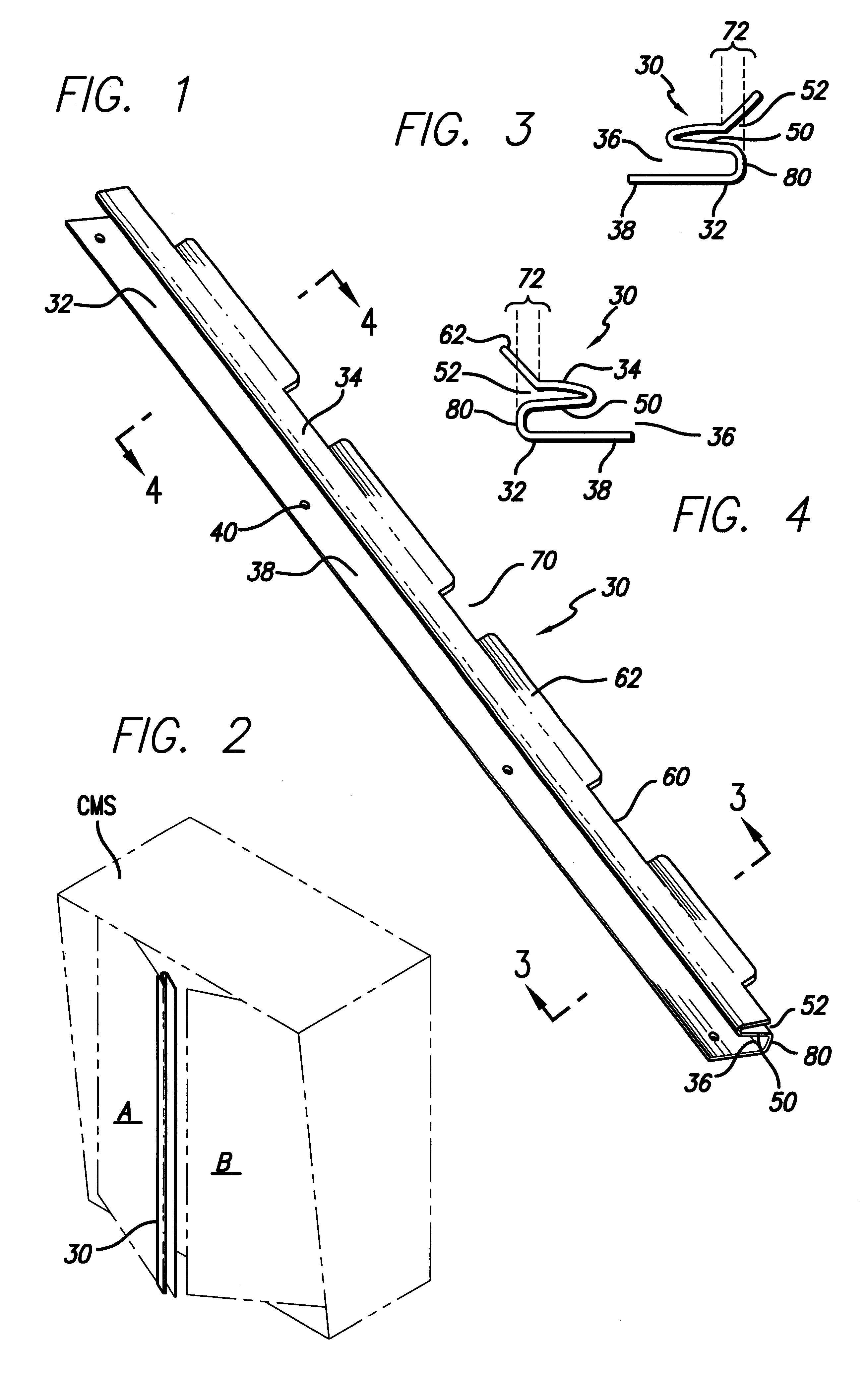
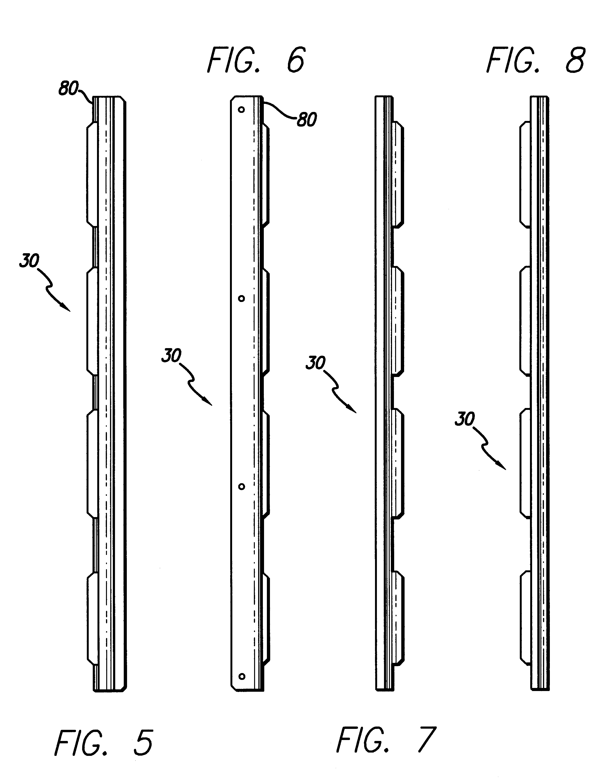
Beginning with FIG. 1, the interlocking door seam 30 of the present invention is shown with its concave 32 and convex 34 strips. The interlocking door seam 30 may be made of tempered steel or the like in order to provide strength and structural integrity, particularly should it be subject to attack by a prybar or the like. The concave strip ...


PUM


Abstract

An interlocking door seam provides a stronger seam for double doors, making them less subject to attack by prybars and the like. Particularly for central mail stations (CMS) and central box units CBU, double doors present there are subject to attack by prybars and the like that force the locks and allow thieves to rifle the contents of the enclosed mail boxes. Attachment of interlocking door seam to the first edge of the first double doors protects that first edge from prybar attacks. The adjoining edge of the second double door then releasably fits into a convex strip that protects the adjoining edge of the second double door, thereby protecting it from prybar attack. The interlocking door seam allows normal operation of the double doors while decreasing the risk to the central mail station of prybar attack at the seam between the double doors. Flanges present along the free edge of the convex strip provide easy engagement of that free edge. Gaps between such flanges accommodate shelving inside the central mail station. Construction of the interlocking door seam by tempered steel or hard and durable materials provides enhanced protection from prybar attack. Additionally, a main access door bolt bracket may serve to better secure and close the double doors, thwarting forced entry therethrough. The individual mailbox slot doors may have hooked cams to provide fail-safe closure.

Description

1. Field of the InventionThis invention relates to door protection and the like and more particularly to a reinforced cluster box having pry-proof seams for interlocking mail station doors.2. Description of the Related ArtIn the past, mail boxes for the delivery and receipt of mail have been associated with individual dwellings such as single family residences. The mailperson on foot could deliver mail to the mail box, or by driving a mail truck or the like, deliver the mail to mail boxes situated adjacent to the road.Recently, tampering with mail left in such mail boxes has become a problem such that the mail must be secured under lock and key. This also provides some privacy for the recipient of the mail. Additionally, central box units or central receiving stations are often installed in new home developments. These central units contain a plurality of individual mail boxes for several of the residents in the adjacent area. The mailperson then only has to stop at the central stat...

Claims


Application Information

Patent Timeline
Patent Type & Authority Patents(United States)
IPC IPC(8): A47G29/12A47G29/00A47G29/16E05B17/20E06B5/10E06B5/11E06B3/36E06B3/32E05B17/00
CPCA47G29/1201A47G29/16E05B17/2003E06B3/365E06B5/113
Inventor NOBLET, C. DALEPACKER, STEPHEN R.
Owner CANAM MARKETING
Why Eureka
Try Eureka