Rotor assembly

a rotor and compressor technology, applied in the direction of bearings, shafts, motors, etc., can solve the problems of increasing the stiffness prolonging the life of the bearing assembly, and increasing the first flexural natural frequency, so as to reduce the load of the bearing assembly due to impeller imbalance, prolong the life of the bearing assembly, and reduce the cantilever length of the rotor assembly

Active Publication Date: 2017-04-18
DYSON TECH LTD
View PDF81 Cites 3 Cited by
  • Summary
  • Abstract
  • Description
  • Claims
  • Application Information

AI Technical Summary

Benefits of technology

[0006]By having a bearing assembly that is located at least partly within the profile of the impeller, loading of the bearing assembly due to impeller imbalance is significantly reduced. Consequently, the lifespan of the bearing assembly is prolonged. Additionally, by locating the bearing assembly within the profile of the impeller, the cantilever length of the rotor assembly is reduced. This then increases the stiffness of the rotor assembly, which in turn results in a higher first flexural natural frequency. Consequently, the rotor assembly is able to operate at much higher sub-critical speeds.
[0007]In having a bearing assembly that comprises a pair of spaced bearings surrounded by a common sleeve, a first portion of the bearing assembly may be located inside the impeller profile while a second portion may be located outside the impeller profile. The portion located outside of the impeller may then be secured to a frame, housing or the like. Consequently, the rotor assembly may be secured to a frame or housing over a relatively large surface area, thus ensuring good securement. Moreover, in having a pair of spaced bearings, the bearing assembly provides a good, stable support for the rotor assembly.
[0009]The impeller ideally comprises a hub supporting a plurality of blades and a recess is formed in an end of the hub. The end of the hub is thus spaced radially from the shaft. The bearing assembly is then located at least partly within the recess. The centre-of-mass of the impeller is typically located between the two axial ends of the hub. By locating the bearing assembly within a recess in the hub, the bearing assembly may be located closer to the centre-of-mass of the impeller. Consequently, the cantilever length of the rotor assembly, as well as radial loading arising from impeller imbalance, may be reduced.
[0012]The bearing assembly may overlie the centre-of-mass of the impeller. This then has the advantage that radial loading due to subsequent imbalance in the impeller may be kept to a minimum.
[0015]By locating the bearing assembly at least partly within a recess in the top of the impeller, the bearing assembly is located closer to the centre-of-mass of the impeller. Consequently, loading of the bearing assembly due to impeller imbalance is reduced and the lifespan of the bearing assembly is increased. Additionally, the cantilever length of the rotor assembly is reduced thus increasing the stiffness of the rotor assembly, which in turn enables the rotor assembly to operate at higher sub-critical speeds.
[0018]The bearing assembly may comprise one or more bearings. Advantageously, the bearing assembly takes the form of a bearing cartridge that comprises a pair of spaced bearings surrounded by a common sleeve. As already noted, this then has the advantage that a first portion of the bearing assembly may be located inside the impeller profile while a second portion may be located outside the impeller profile. The portion located outside of the impeller may then be secured to a frame, housing or the like. Additionally, in having a pair of spaced bearings, the bearing assembly provides a good, stable support for the rotor assembly.

Problems solved by technology

Consequently, the lifespan of the bearing assembly is prolonged.
This then increases the stiffness of the rotor assembly, which in turn results in a higher first flexural natural frequency.

Method used


Image

  • Rotor assembly
  • Rotor assembly
  • Rotor assembly

Examples


Embodiment Construction

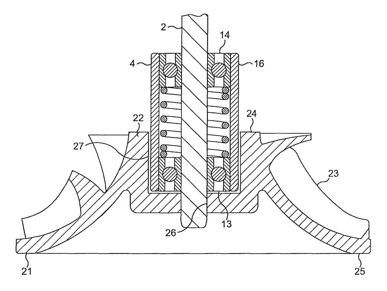
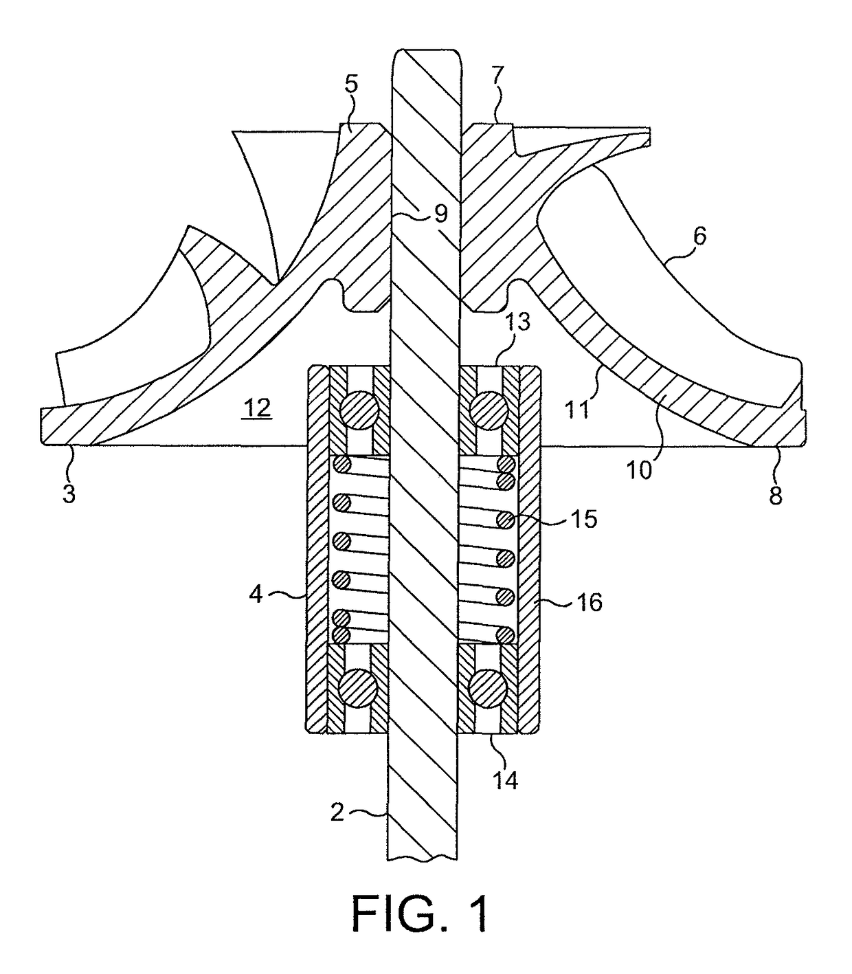
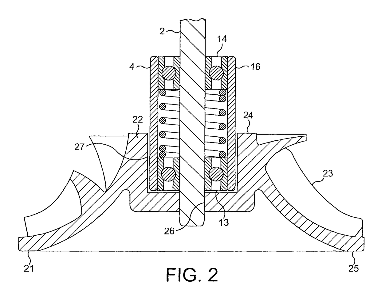
[0025]The rotor assembly 1 comprises a shaft 2 to which are mounted an impeller 3 and a bearing cartridge 4.

[0026]The impeller 3 comprises a hub 5 around which a plurality of blades 6 are supported. The hub 5 extends axially from a top end 7 to a bottom end 8. A central bore 9 extends through the hub 5 into which the shaft 2 is received. The hub 5 includes a dome-shaped wall 10 having a concave inner surface 11 that defines a central recess 12 in the bottom 8 of the hub 5. The recess 12 is greater in diameter than that of the bore 9 such that the bottom end 8 of the hub 5 is spaced radially from the shaft 2.

[0027]The bearing cartridge 4 comprises a pair of spaced bearings 13,14 preloaded by a spring 15 and surrounded by a sleeve 16. The bearing cartridge 4 is mounted to the shaft 2 such that the bearing cartridge 4 projects into the recess 12 formed in the bottom 8 of the hub 5. The bearing cartridge 4 is thus partly located within the profile of the impeller 3, i.e. the region boun...


PUM


Abstract

A rotor assembly that includes a shaft to which are mounted an impeller and a bearing assembly. The bearing assembly is located at least partly within the profile of the impeller so as to reduce loading of the bearing assembly as well as reduce the cantilever length of the rotor assembly.

Description

REFERENCE TO RELATED APPLICATIONS[0001]This application claims the priority of United Kingdom Application No. 0903052.9, filed Feb. 24, 2009, the entire contents of which are incorporated herein by reference.FIELD OF THE INVENTION[0002]The present invention relates to a rotor assembly for a compressor.BACKGROUND OF THE INVENTION[0003]The rotor assembly of a compressor typically comprises an impeller mounted to a shaft that is driven by a motor. Imbalance in the rotor assembly places increased loading on the bearings used to mount the rotor assembly within the compressor, thereby reducing the lifespan of the bearings. The rotor assembly is therefore ideally balanced prior to mounting within the compressor. However, it is not always possible to balance the rotor assembly as a complete unit prior to mounting within the compressor. Instead, it is often necessary to assemble the various components of the rotor assembly within the compressor. Accordingly, while the individual components m...

Claims


Application Information

Patent Timeline
Patent Type & Authority Patents(United States)
IPC IPC(8): F04D29/056F04D29/26F16C19/54F16C25/08
CPCF04D29/0563F04D29/263F16C19/54F16C25/083F16C2360/00F04D29/05F04D29/646F04D17/08F04D29/056F04D29/266
Inventor JONES, DAVID MICHAELMOCKRIDGE, RICHARD IAINBURLINGTON, GEOFFREY MICHAEL
Owner DYSON TECH LTD
Why Eureka
Try Eureka