Adjustable support assembly

a technology of supporting structure and adjustable bracket, which is applied in the direction of machine supports, building scaffolds, other domestic objects, etc., can solve the problems of difficult to securely hold the legs, the support platform is not easily constructed and/or adjusted, and the safety hazards of the leg, etc., to achieve stable support structure, easy construction and/or adjustment, and sufficient play

Inactive Publication Date: 2011-06-07
SMR ACQUISITION
View PDF4 Cites 1 Cited by
  • Summary
  • Abstract
  • Description
  • Claims
  • Application Information

AI Technical Summary

Benefits of technology

[0005]According to the invention, a support assembly that provides a stable support structure while remaining easily constructible and / or adjustable includes a hollow member or sleeve having an internal corner therein and configured to receive a support tube or leg therein. A support tube or leg is configured to be slidably inserted within the hollow member and a mechanism is provided for forcing an outer corner of the support tube into the internal corner of the hollow receiving member. In this way the leg is tightened against the internal corner and two sides of the sleeve, rather than against only one side of the sleeve. This provides a much more secure connection between the leg and the sleeve while still allowing sufficient play of the leg, when loosened, in the sleeve for easy construction of the structure and adjustment of the leg. In addition, if desired, the sides of the sleeve or the leg can be provided with elongate projections which reduce the surface areas in contact between the sleeve and the leg to reduce resistance to sliding of the leg in the sleeve to therefore make initial assembly and later adjustment of the leg with respect to the sleeve easier, particularly when the leg and / or sleeve are made of aluminum or aluminum alloy. It has been found that the normal square receiving sleeve and normal square leg can be modified by flattening one corner of the square to form a small fifth side of both the sleeve and leg which is opposite one of the corners of the square. By placing a set screw or other tightening mechanism in this fifth side of the sleeve to press against the fifth side of the leg, the leg can be pressed into the corner of the sleeve opposite the fifth side of the sleeve. This provides a much better securement of the leg in the sleeve than can be achieved with the square sleeve and square leg received therein and tightening the square leg against one side of the square sleeve.

Problems solved by technology

However, often the tube moves within the sleeve thereby creating a safety hazard, particularly where adjustability of the leg with respect to the structure is desired.
The screw has to be tightened sufficiently to secure the leg in desired position, however, the play required to allow the leg to slide in the sleeve for adjustment purposes makes it difficult to securely hold the leg.
If the tube and sleeve are sufficiently fitted together to prevent movement, the support platform is not easily constructed nor easily adjusted.
The resulting friction, particularly if the sleeve and / or the leg is made of aluminum or aluminum alloy, can make sliding adjustment difficult.

Method used


Image

  • Adjustable support assembly
  • Adjustable support assembly
  • Adjustable support assembly

Examples


Embodiment Construction

)

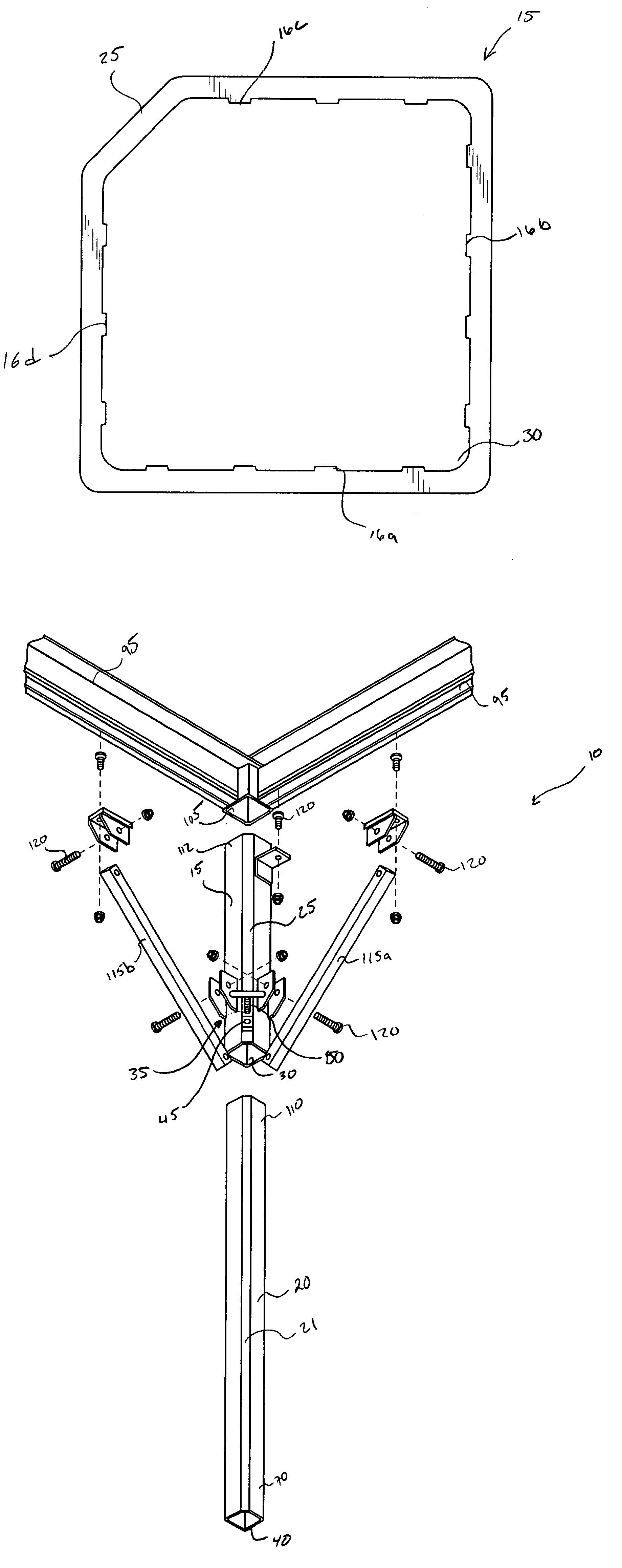
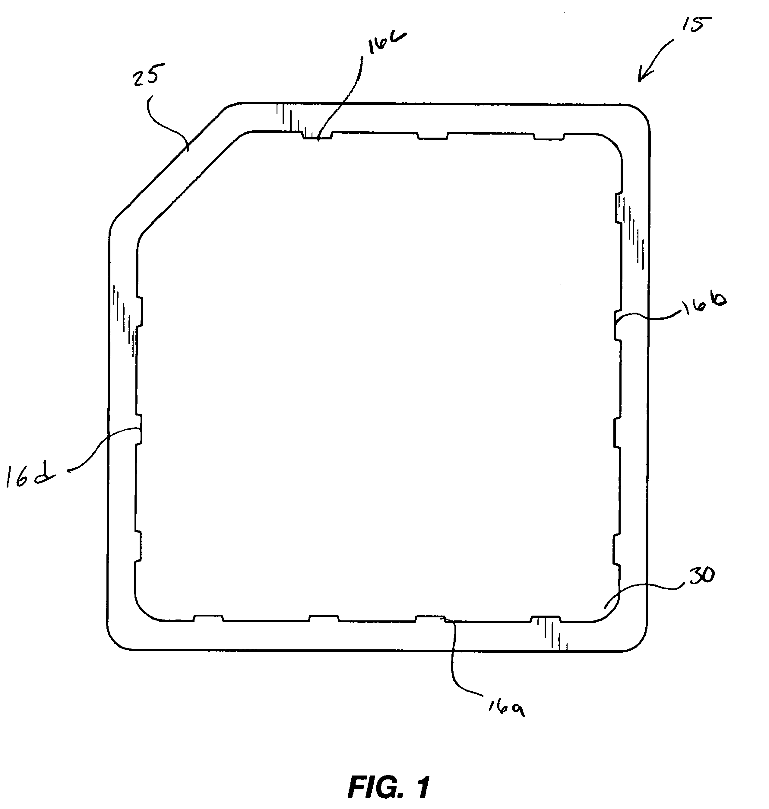
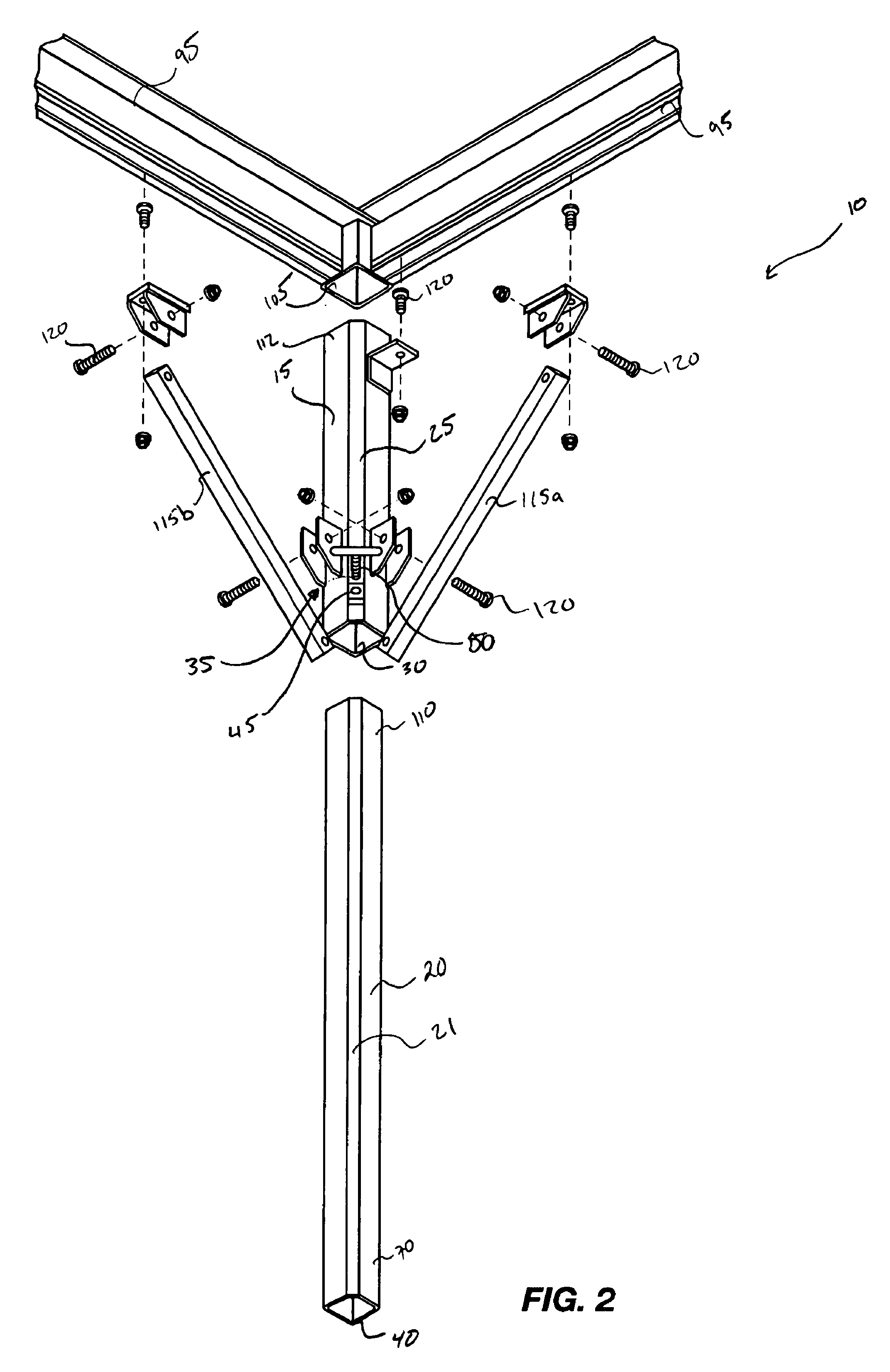
[0019]As illustrated in FIGS. 1 and 2, a support system, indicated generally at 10, in an example implementation in accordance with the invention comprises a longitudinally extending hollow member 15 configured to receive a support tube 20 therein, the longitudinally extending hollow member 15 comprising an approximately flat surface 25 opposite an internal corner 30 of the longitudinally extending hollow member 15. The support tube 20 is configured to be removably inserted within the longitudinally extending hollow member 15 and a mechanism 35, FIG. 2, for forcing an outer corner 40 of the support tube 20 into the internal corner 30 of the longitudinally extending member 15 is provided. The support tube 20 has a flat surface 21 corresponding to flat surface 25 of the longitudinally extending hollow member 15. In general, the support system 10 comprises a means for securing support tube 20 within a longitudinally hollow extending member 15 (sometimes referred to as a longitudinally...


PUM


Abstract

A support structure is disclosed comprising a longitudinally extending hollow member configured to receive a support tube therein. The longitudinally extending hollow member comprises an approximately flat surface opposite an internal corner of the longitudinally extending hollow member. The invention further comprises a support tube configured to be removably inserted within the longitudinally extending hollow member and a mechanism for forcing an outer corner of the support tube into the internal corner of the longitudinally extending member.

Description

BACKGROUND[0001]1. Field[0002]The present invention relates generally to support assemblies. More particularly, the present invention relates to an adjustable platform support structure such as a dock structure.[0003]2. State of the Art[0004]Over the years, various arrangements have been produced to support platform assemblies. For example, a tube and sleeve configuration have been used to connect upper platform surfaces to support legs for a variety of support platforms. However, often the tube moves within the sleeve thereby creating a safety hazard, particularly where adjustability of the leg with respect to the structure is desired. For example, a square hollow member secured to the structure may form a sleeve to slidably receive a square support tube therein forming a support leg for the structure. When the leg is slid to a desired position in the sleeve, a set screw or bolt extending through one side of the square hollow sleeve member is tightened against the adjacent side of ...

Claims


Application Information

Patent Timeline
Patent Type & Authority Patents(United States)
IPC IPC(8): F16M11/20
CPCE02B3/068
Inventor SMITH, TODDHORGEN, LINDSAY
Owner SMR ACQUISITION
Why Eureka
Try Eureka