Cable connector plate and method for interconnecting ends of fiber optic cable

a technology of fiber optic cable and connector plate, which is applied in the direction of optics, fibre mechanical structures, instruments, etc., can solve the problem of substantially increasing the cable bend radius, and achieve the effect of convenient and convenient interconnection of fiber

Inactive Publication Date: 2001-06-26
DITEL +1
View PDF18 Cites 166 Cited by
  • Summary
  • Abstract
  • Description
  • Claims
  • Application Information

AI Technical Summary

Benefits of technology

It is another object of the invention to provide a connector plate for a fiber optic cable management cabinet which allows the use of a maximum amount of space inside the cabinet for routing and ...

Problems solved by technology

Because the angle of each of the adapters is the same, however, the plate will actually substantially i...

Method used


Image

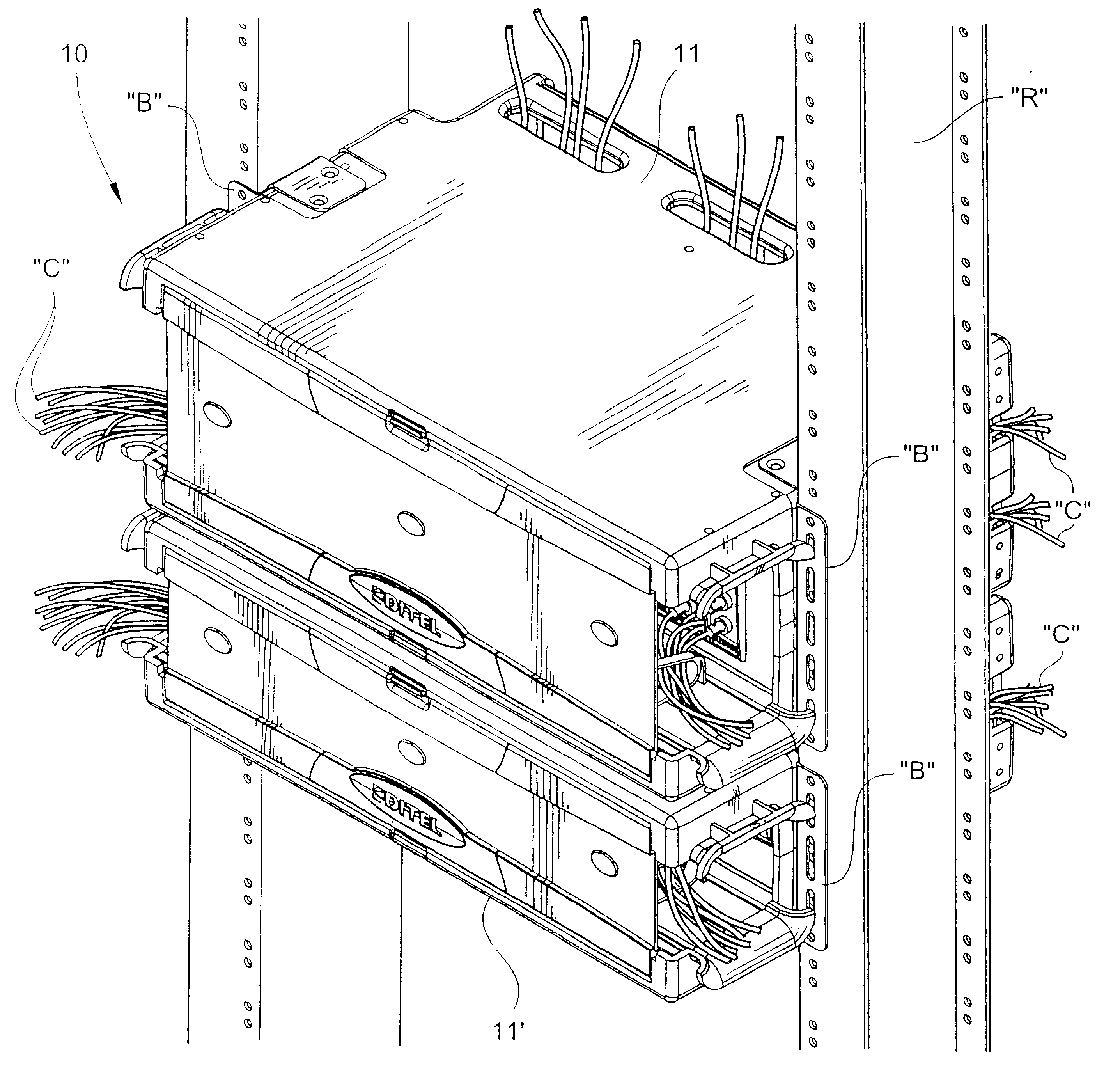
  • Cable connector plate and method for interconnecting ends of fiber optic cable
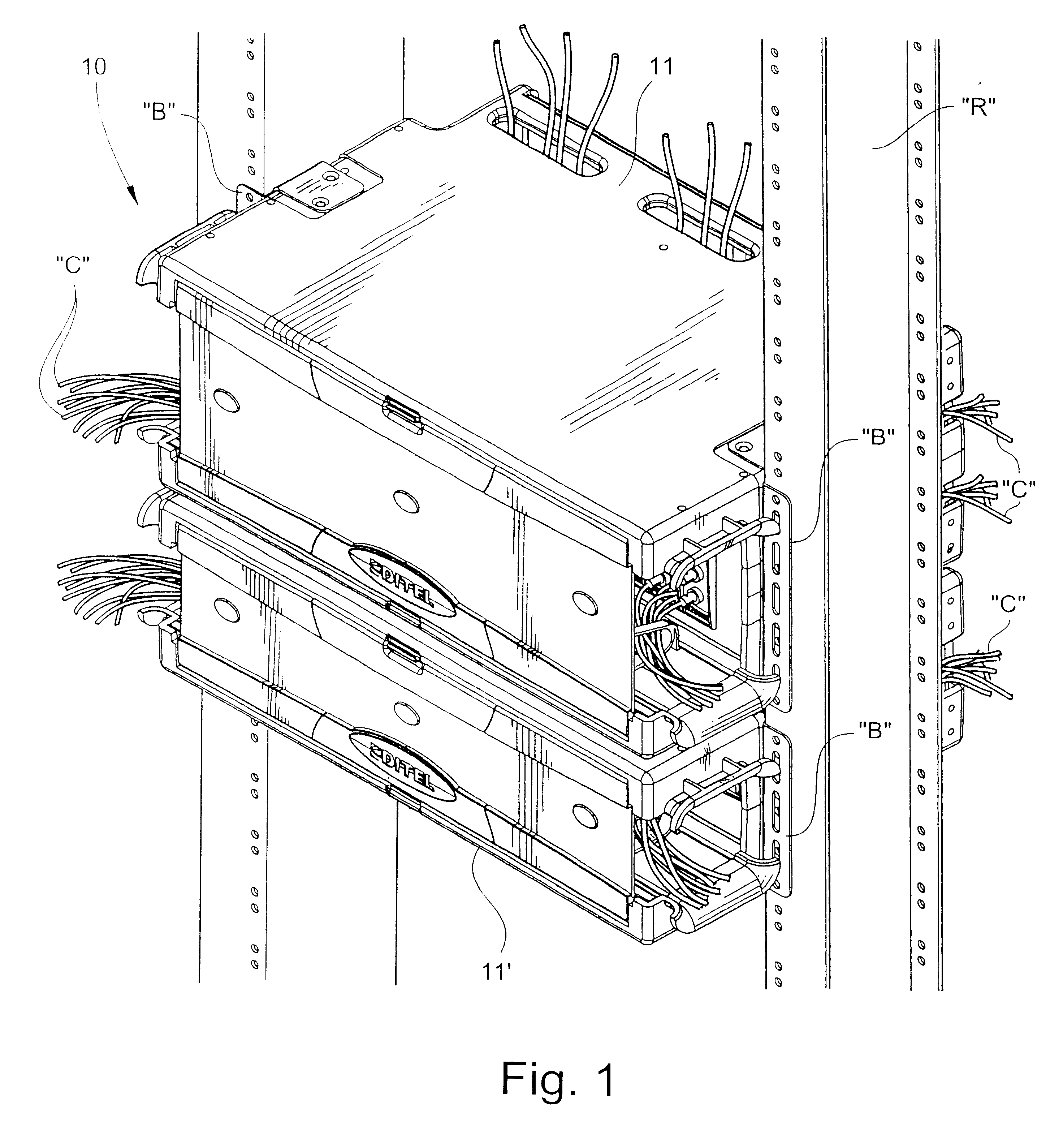
  • Cable connector plate and method for interconnecting ends of fiber optic cable
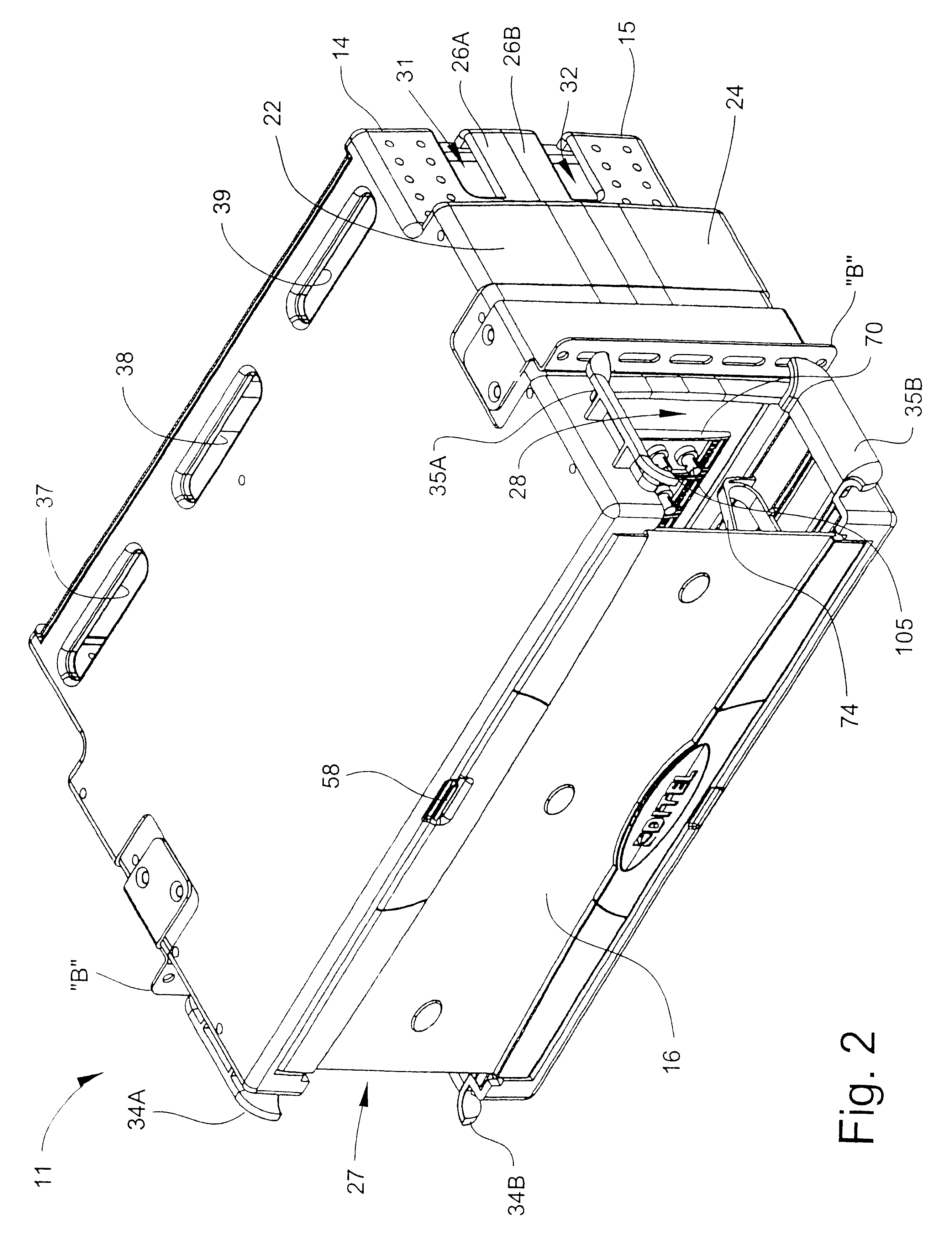
  • Cable connector plate and method for interconnecting ends of fiber optic cable

Examples


third embodiment

a cable connector plate 70C is shown in FIG. 15. The connector plate 70C includes a base 71 with integrally-formed angled steps 71A-71F, and respective openings formed in the steps 71A-71F for receiving and holding adapters 105C at distinct angles relative to a notional plane "P" facing either of the front and back sides of the plate 70C such that the adapters 105C extend along respective intersecting axes. According to one embodiment, each adapter 105C is formed in two halves with axiallyaligned end portions projecting outward from each of the front and back sides of the base 71. The angle "A'" of the first, top adapter is approximately 70 degrees. The corresponding angle of the second adapter is approximately 74 degrees. The angle of the third adapter is approximately 78 degrees. The angle of the fourth adapter is approximately 82 degrees. The angle of the fifth adapter is approximately 86 degrees. The angle of the sixth and bottom adapter is approximately 90 degrees. By angling t...


PUM


Abstract

A cable connector plate interconnects ends of fiber optic cable. The connector plate includes a base having opposing front and back sides. At least three adapters are carried by the base and have respective axially-aligned end portions extending outwardly from each of the front and back sides of the base. The adapters receive and interconnect ends of fiber optic cable in optical alignment. The adapters are disposed at respective distinct angles relative to a notional plane facing either of the front and back sides of the base.

Description

TECHNICAL FIELD AND BACKGROUND OF THE INVENTIONThis invention relates generally to fiber optic cable management within an area such as a telecommunications central office, headend for fiber optic television cable, or wiring closet, and more particularly to a cable connector plate and method for operatively interconnecting ends of fiber optic cable. Connector plates of the type according to the present invention are typically located inside cable management cabinets mounted on vertical racks and having access openings for receiving and distributing fiber optic cable. Fiber optic cable exiting the cabinet is generally routed through a raceway assembly, such as described in Applicant's copending application Ser. No. 09 / 220,267. The complete disclosure of this application is incorporated herein by reference.According to one prior art cable connector plate described in U.S. Patent No. 4,824,196, a number of cable adapters are carried by a base and arranged in a single row at identical an...

Claims


Application Information

Patent Timeline
IPC IPC(8): G02B6/38G02B6/44
CPCG02B6/3897G02B6/4452
Inventor JOHNSTON, DARE P.MATTEI, MICHAELAUTERI, ROBERT P.HANI, ERWIN F.HERDA, MICHAEL T.MUSKE, STEVEN J.SUTTIE, DAVID W.
Owner DITEL
Why Eureka
Try Eureka