Mold assembly for forming ophthalmic lens

a technology of ophthalmic lenses and mold cavities, which is applied in the direction of foundry moulding apparatus, instruments, foundry patterns, etc., can solve the problems of unplanned edge profile of ophthalmic lenses to be obtained, unfavorable mold cavity configuration with respect to nominal design,

Inactive Publication Date: 2001-07-10
MENICON CO LTD
View PDF8 Cites 33 Cited by
  • Summary
  • Abstract
  • Description
  • Claims
  • Application Information

AI Technical Summary

Problems solved by technology

The mold assembly disclosed in the U.S. Patent, however, suffers from various problems.
Further, if the knife-edge portion is not formed with high accuracy of configuration, the ophthalmic lens to be obtained does not have an intended edge profile.
In the thus formed mold assembly, if the mating surfaces of the two molds are not accurately aligned or engaged with each other, the configuration of the mold cavity may undesirably have a deviation with respect to the nominal design.
In particular, the obtained ophthalmic lens does not have an intended edge profile due to the misalignment of the mating surfaces of the two molds.
The clamping force applied to the molds, however, may cause deformation of the molds, undesirably resulting in a change in the spherical degree of the ophthalmic lens to be obtained and a change in the volume of the mold cavity.

Method used


Image

  • Mold assembly for forming ophthalmic lens
  • Mold assembly for forming ophthalmic lens
  • Mold assembly for forming ophthalmic lens

Examples


Embodiment Construction

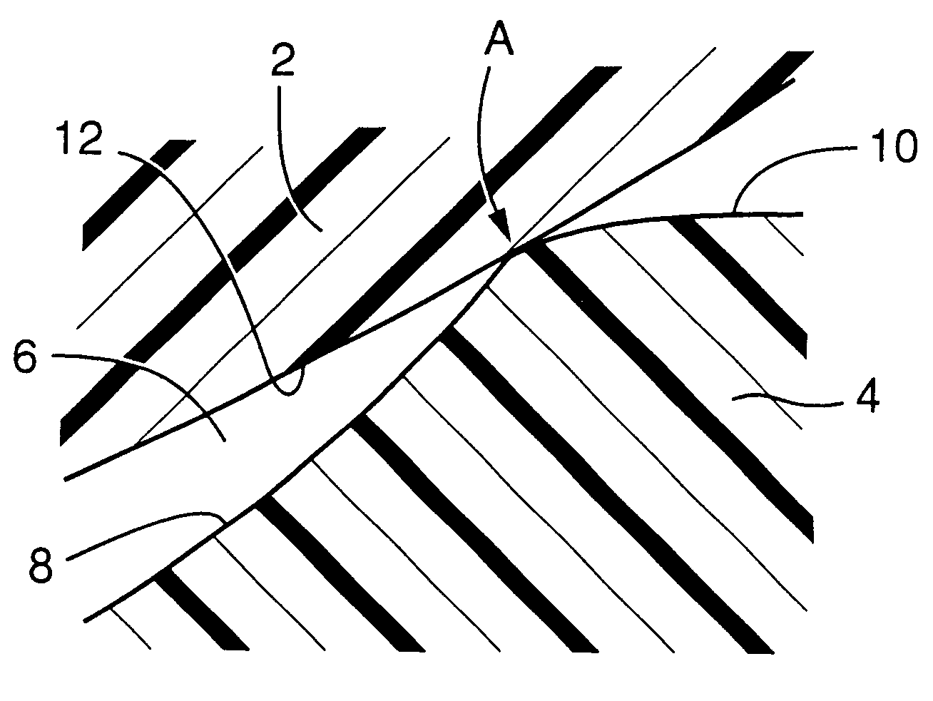
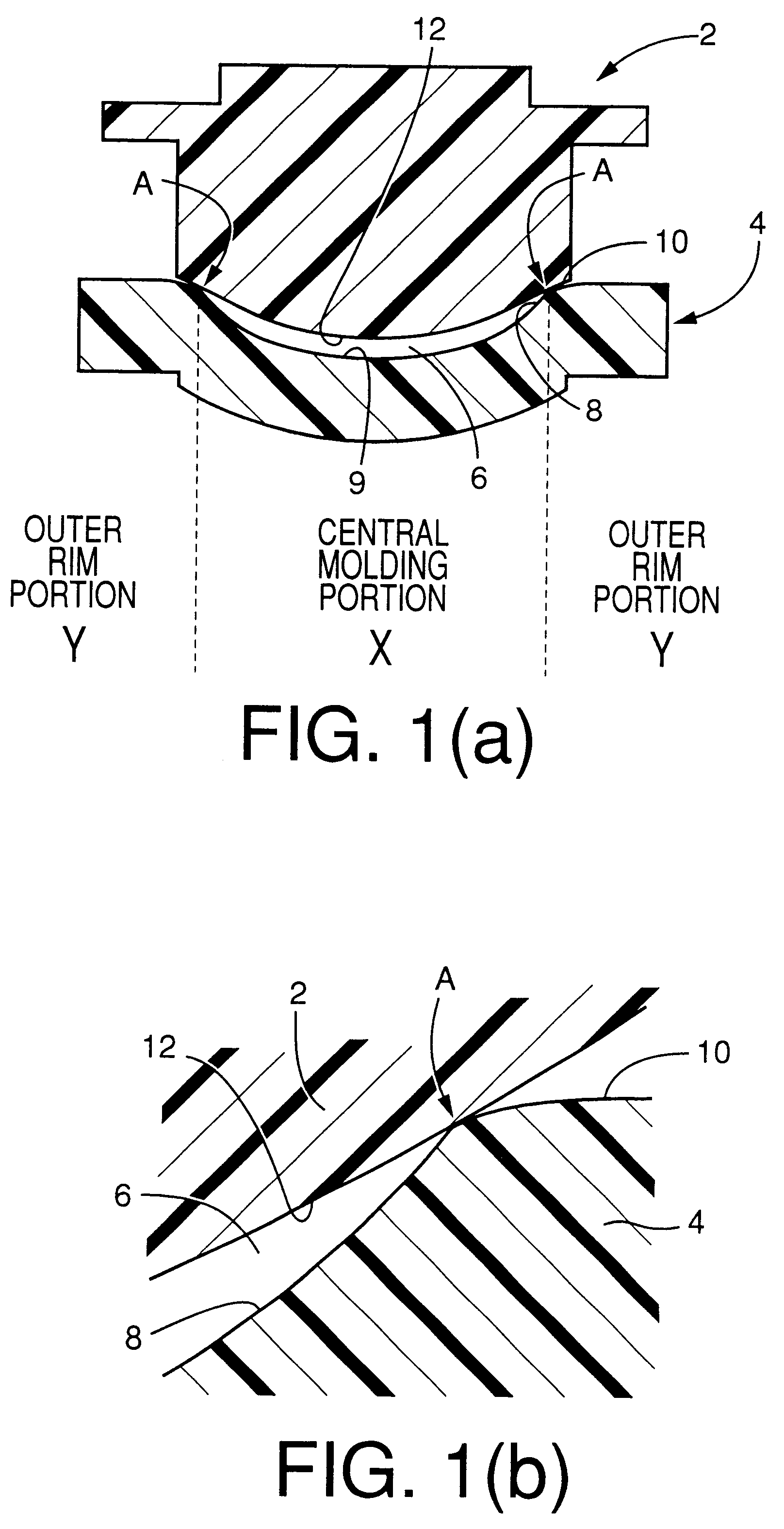
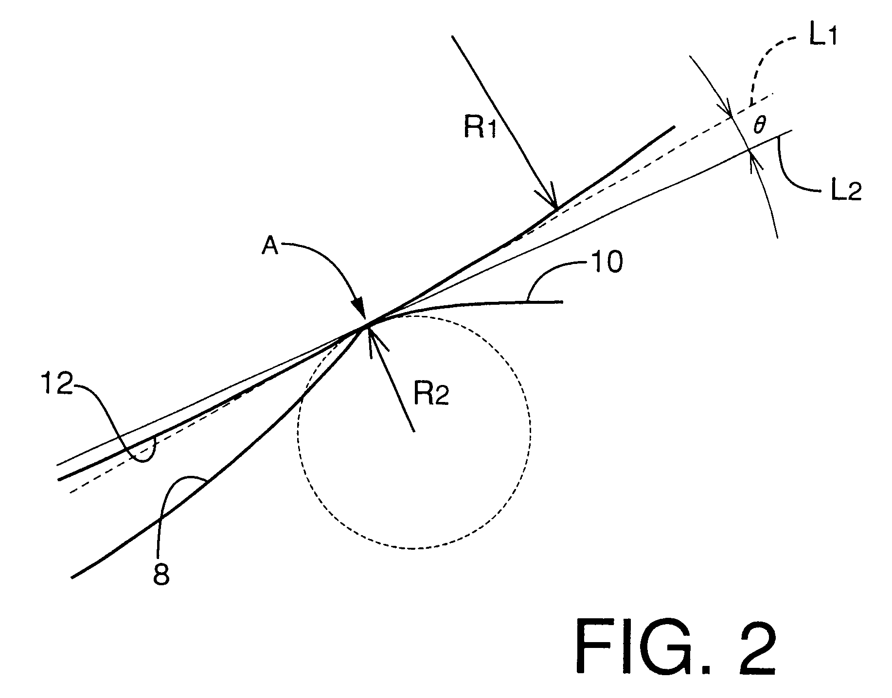
The mold assembly consisting of the male mold 2 and the female mold 4 shown in FIGS. 1 and 2 were formed of polypropylene in a known molding process. Described in detail, the male and female molds 2, 4 were configured such that the contact lens to be obtained has a diameter of 13.5 mm, and a rear optical surface having a radius of curvature of 7 mm and a front optical surface having a radius of curvature of 8 mm. The rear optical surface is given by the mold surface 12 of the male mold 2, and the front optical surface is given by the lens-forming region 9 including the concave portion 8 of the female mold 4. Further, the radius of curvature R.sub.2 of the convex portion 10 of the female mold 4 at the radial position A was 0.2 mm, while the angle .theta. formed by the tangent lines L.sub.1 and L.sub.2 was 5.degree..

In the meantime, a liquid composition for a contact lens was prepared as the polymeric lens material 26, which composition included 100 parts by weight of 2-hydroxyethyl m...


PUM

PropertyMeasurementUnit
diameteraaaaaaaaaa
diameteraaaaaaaaaa
diameteraaaaaaaaaa

Abstract

Lens mold assembly including a first and a second mold cooperating with each other to define a mold cavity for molding an ophthalmic lens with the first and second molds being held in line contact with each other at a radial position, wherein at least one of the two molds consists of a central molding portion located radially inwardly of the radial position, and an outer rim portion located radially outwardly of the radial position, the central molding portion cooperating with the other mold to define the mold cavity, the above-indicated at least one mold having a mold surface which is opposed to a mold surface of the other mold when the two molds are assembled together, the mold surface of the at least one mold consisting of a central lens-forming region in the central molding portion, and an outer peripheral non lens-forming region in the outer rim portion, at least a part of the lens-forming region adjacent to the radial position providing a concave portion, while at least a part of the outer peripheral non lens-forming region adjacent to the radial position providing a convex portion.

Description

FIELD OF THE ARTThe present invention relates to a mold assembly for forming an ophthalmic lens such as a contact lens or an intraocular lens. More particularly, the invention is concerned with such a mold assembly which does not need a sharp annular protrusion or edge portion such as a knife-edge portion for defining an edge of the ophthalmic lens.DISCUSSION OF THE RELATED ARTThere have been proposed various techniques for producing an ophthalmic lens by a mold assembly consisting of a first mold and a second mold in the form of a male mold and a female mold or an upper mold and a lower mold, which are assembled together so as to define therebetween a mold cavity having a configuration that gives the intended ophthalmic lens such as a contact lens or an intraocular lens. The mold cavity defined upon closing or assembling of the first and second molds is filled with a suitable lens material to mold the intended ophthalmic lens.To define the mold cavity between the two molds, the two...

Claims


Application Information

Patent Timeline
Patent Type & Authority Patents(United States)
IPC IPC(8): B29C33/42B29D11/00B29C35/08G02C7/02B29C39/26B29K67/00B29K105/32B29L11/00
CPCB29C33/42B29D11/00125B29D11/00057B29C2035/0827Y10S425/808
Inventor TOGO, MOTONOBUISHIHARA, KENICHI
Owner MENICON CO LTD
Why Eureka
Try Eureka