Transition from a waveguide to a strip transmission line

a technology of transmission line and waveguide, which is applied in the direction of electrical equipment, multiple-port networks, coupling devices, etc., can solve the problems of ridge breaking off from the waveguide wall, manufacturing difficulty, and relatively expensive conventional transition from waveguide to striplin

Inactive Publication Date: 2001-07-24
ROBERT BOSCH GMBH +1
View PDF6 Cites 131 Cited by
  • Summary
  • Abstract
  • Description
  • Claims
  • Application Information

AI Technical Summary

Problems solved by technology

From the aspect of manufacturing technology, this conventional transition from a waveguide to a stripline is relatively costly.
This form of the ridge makes manufacturing difficult, particularly if the waveguide is to b...

Method used


Image

  • Transition from a waveguide to a strip transmission line
  • Transition from a waveguide to a strip transmission line
  • Transition from a waveguide to a strip transmission line

Examples


Embodiment Construction

In the following, like references numerals refer to like parts.

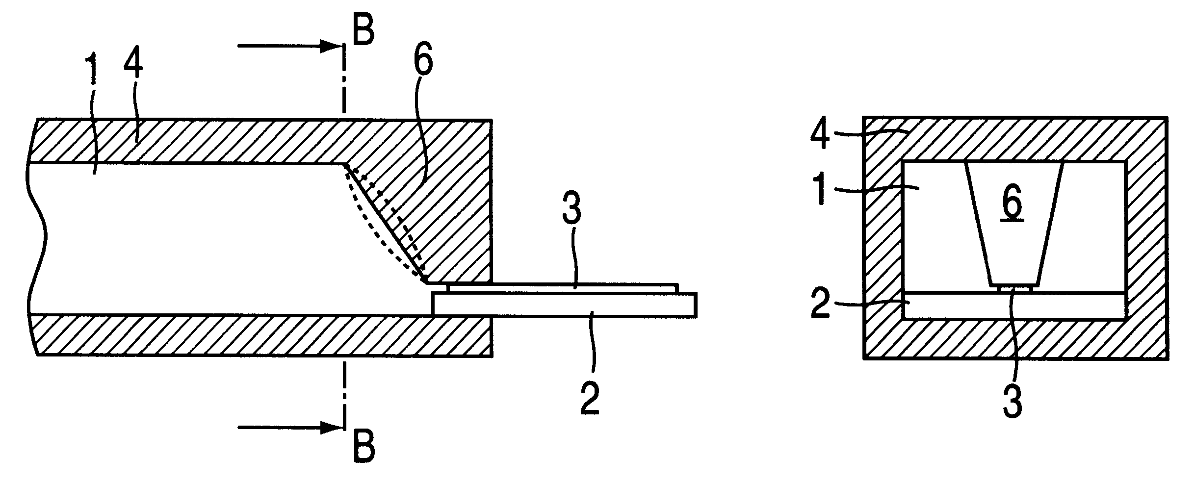
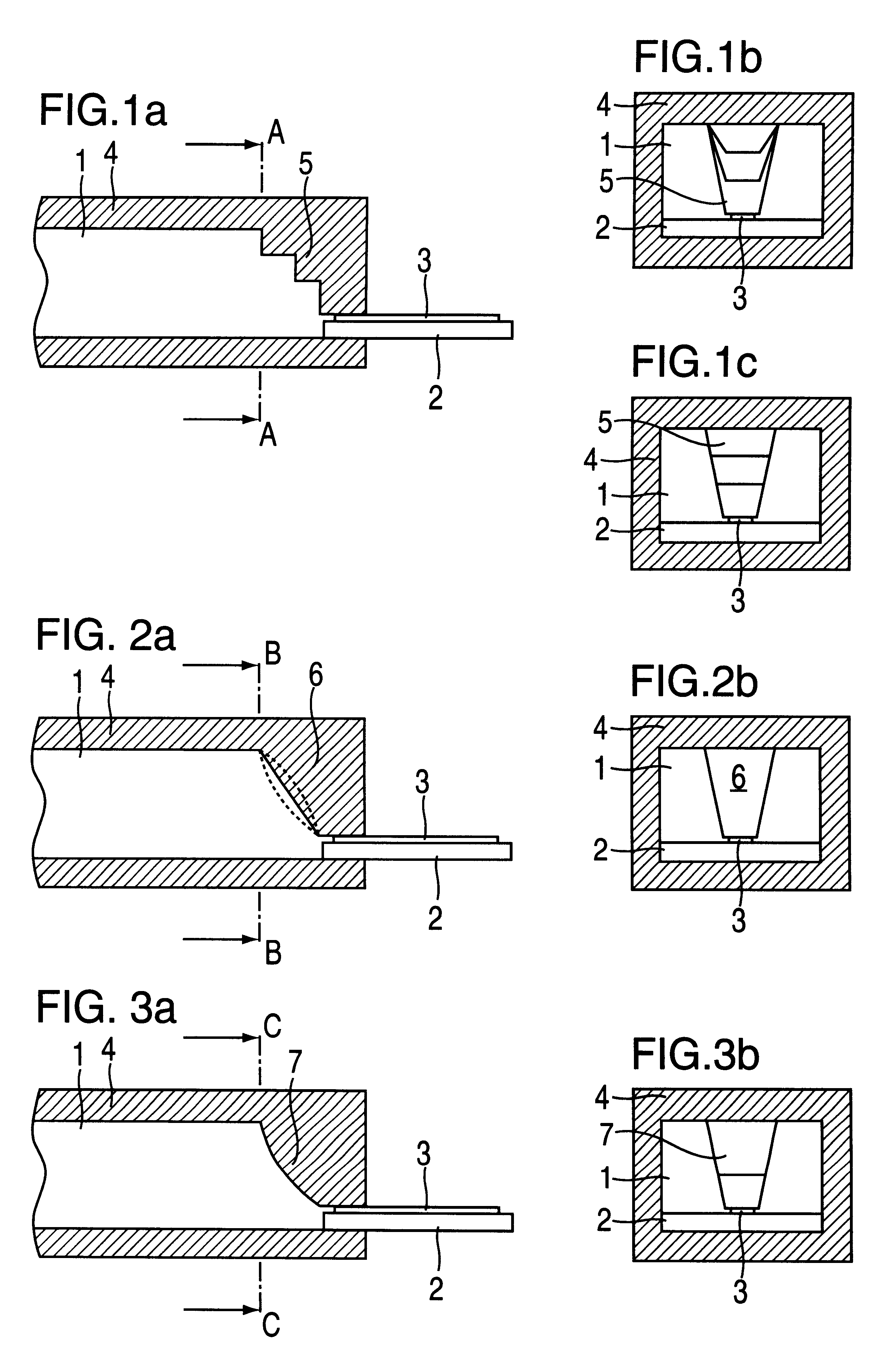
In FIG. 1a, a cross section through a waveguide 1 is depicted, which transitions onto a stripline 3 supported by a substrate 2. For the transition from waveguide 1 to stripline 3, there is a ridge 5 on the wall of the waveguide 4 across from the stripline 3, the ridge running in the longitudinal direction of waveguide 1 and its height increasing in the direction of the stripline 3 in steps. This ridge 5, which forms a cross-section transformation, is bonded to stripline 3 at the point which forms the smallest waveguide cross section. Bonding can take place in various ways. For example, substrate 2 with stripline 3 can, as can be seen in FIG. 1a, be inserted into waveguide 1 below ridge 5 so that ridge 5 lies against stripline 3 and can be bonded to it through soldering or gluing. Ridge 5 can also be bonded via a conductive ribbon to stripline 3 which terminates in front of waveguide 1.

In FIG. 1b, a cross section A--A thr...


PUM


Abstract

In order for it to be possible to manufacture a transition with a cost-effective stamping or diecasting or cold-molding process or with a plastic injection-molding process with subsequent metal plating, at least one ridge situated in the waveguide, which reduces the waveguide cross section in the direction of the stripline, has a cross section which tapers conically in the direction of the stripline.

Description

The present invention relates to a transition from a waveguide to a stripline in which the waveguide has at least one ridge which reduces the waveguide cross section in the direction of the stripline.BACKGROUND INFORMATIONA conventional transition from a waveguide to a stripline is described in a textbook by Reinmund Hoffmann, Integrierte Mikrowellenschaltung (Integrated Microwave Circuitry), Springer-Verlag 1983, pages 90, 91. As disclosed in this publication, the stepped ridge, which in bonded to the stripline, has a rectangular cross section and is mounted as a separate part in the waveguide. From the aspect of manufacturing technology, this conventional transition from a waveguide to a stripline is relatively costly.In a transition from a waveguide to a stripline described in Japan Patent No. 05 090807, a ridge having a change in height which is continuous in stages is arranged in the waveguide. The cross-sectional shape of the ridge tapers perpendicularly to the longitudinal ax...

Claims


Application Information

Patent Timeline
IPC IPC(8): H01P5/107H01P5/10
CPCH01P5/107
Inventor SCHMIDT, EWALDVOIGTLANDER, KLAUSMAYER, HERMANNLUCAS, BERNHARDDENNERLEIN, GERDBEEZ, THOMASMULLER, ROLANDOLBRICH, HERBERTMARTIN, SIEGBERTDUTZI, JOACHIMBIRD, JOHNDAWSON, DAVID NEILNASH, COLINPRIME, BRIANPETTIT, CYRIL EDWARD
Owner ROBERT BOSCH GMBH
Why Eureka
Try Eureka