Power plug assembly

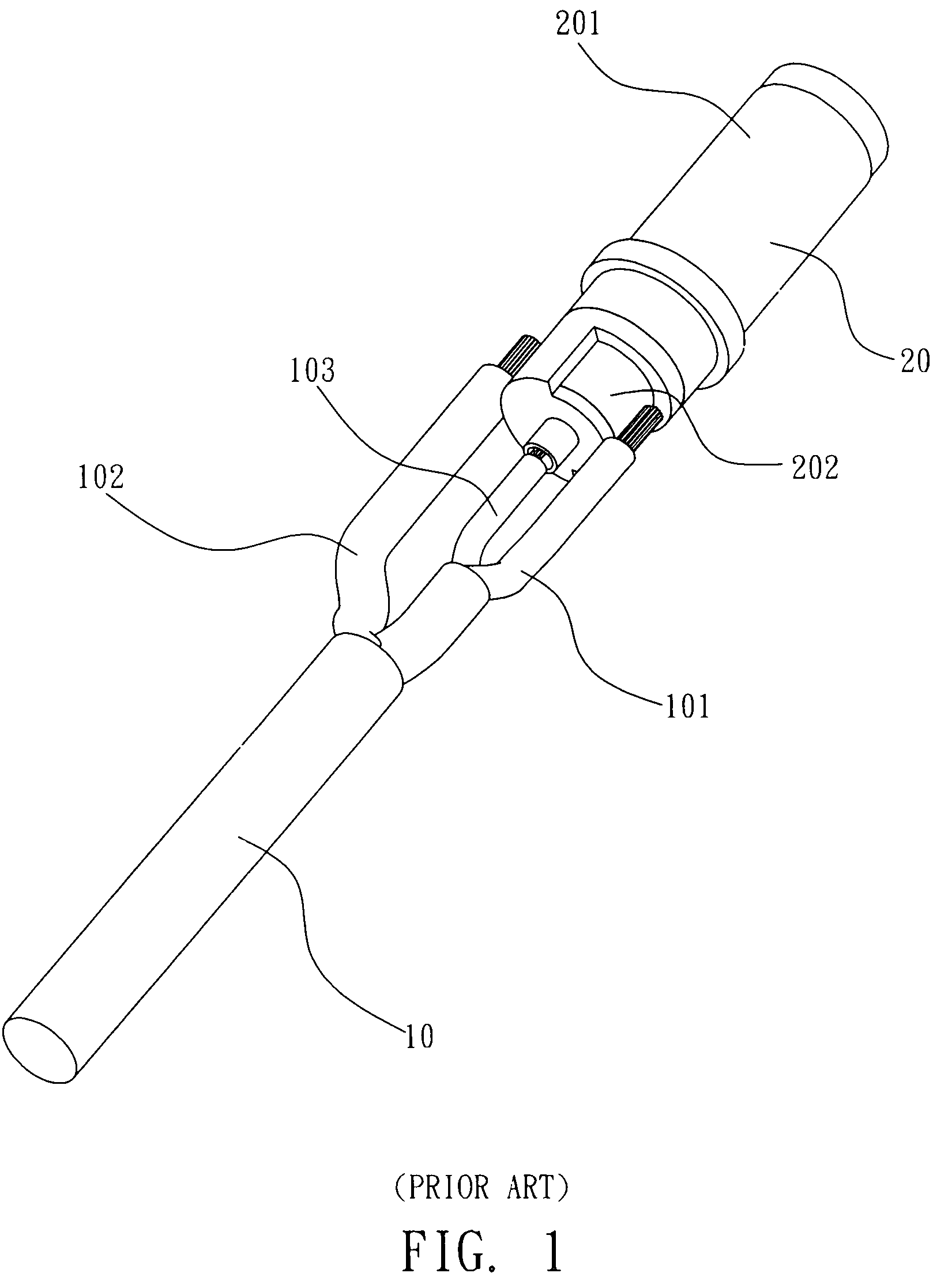
a technology of power plugs and components, applied in the direction of coupling device details, coupling device connections, electric discharge lamps, etc., can solve the problems of difficult welding operation, large tin points of welding locations, and forming malfunction products, so as to achieve enhanced connection strength of cable and conductive sleeve tubes

Inactive Publication Date: 2010-03-16
TAIWAN LINE TEK ELECTRONICS
View PDF8 Cites 23 Cited by
  • Summary
  • Abstract
  • Description
  • Claims
  • Application Information

AI Technical Summary

Benefits of technology

[0005]The applicant of the present invention has devoted himself to design and commercially distribute power plus, power sockets and cables and been trying to overcome the disadvantages of directly welding the cable of the power plug assembly on the conductive sleeve tube as mentioned above; and by overcoming the disadvantages, the connecting strength of the cable and the conductive sleeve tube can be enhanced; after try and error the present invention of power plug assembly is provided.
[0006]One object of the present invention is to overcome disadvantages that welding points formed during an welding operation processed on a conventional cable and a conductive sleeve tube are relatively too big and plural copper wires are in a spread-out status so the welding operation is harder to proceed, the present invention provides a fashion that terminals are connected to end sections of wires of a cable in advance, then the terminals are respectively welded on corresponding locations of a conductive sleeve tube so the connecting strength is enhanced. With the welding fashion provided by the present invention, following advantages are achieved: a.) effectively reducing sizes of tin points at the welding locations, b.) welding of the terminals and the conductive sleeve tube is easier so the welding speed and the production capacity are increased, and c.) by providing retaining members on a positive and a negative terminals, a printed circuit board or any other functional electronic unit, e.g. a LED or a detecting IC for indicating or detecting, can be provided between the positive and the negative terminals.

Problems solved by technology

Speaking of fashions of connection, an welding operation is an inevitable process for a power-supplying plug, but disadvantages of such art is that when plural exposed copper wires at the end sections of the wires are welded on the conductive sleeve tube 20, the tin points of the welding locations are relatively too big, so when an operation of embedded-type plastic injection molding is processed, the mold of the plastic injection molding will press on the welded tin points or even break the copper wires, a malfunction product is therefore formed.
After the plural copper wires at the end sections of the wires are pressed by welding tools, the wires will be in a spread-out status so the welding operation is harder to proceed.

Method used


Image

  • Power plug assembly
  • Power plug assembly
  • Power plug assembly

Examples


Embodiment Construction

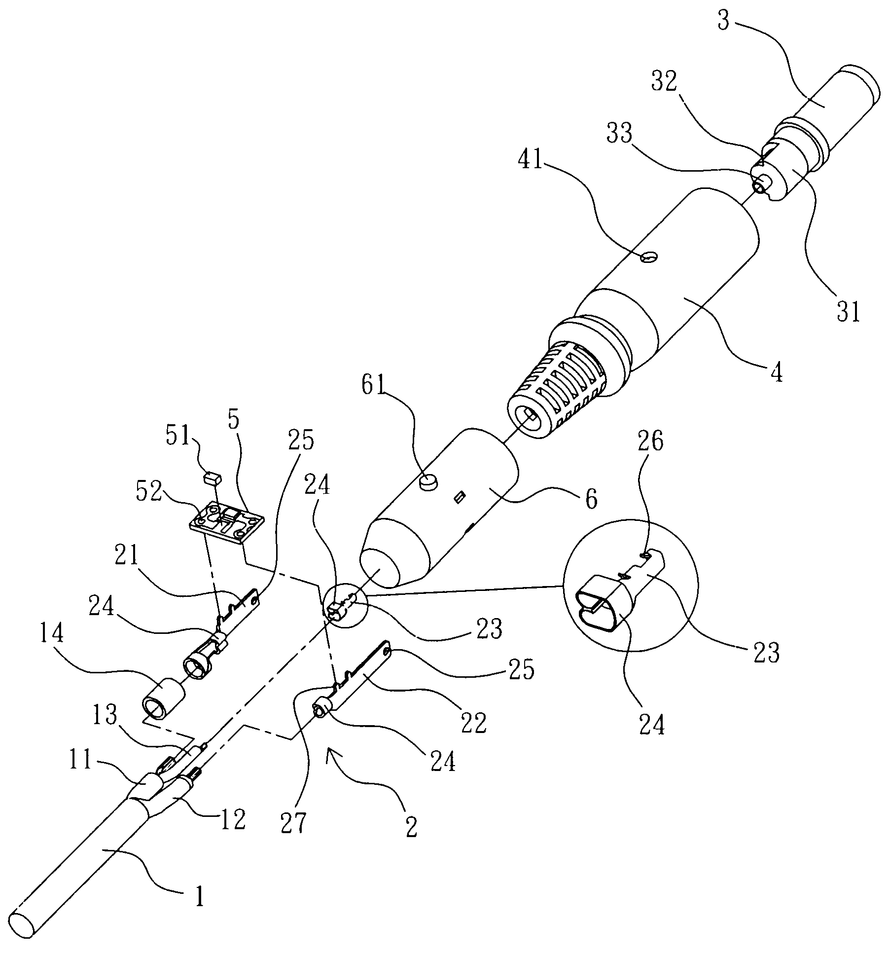
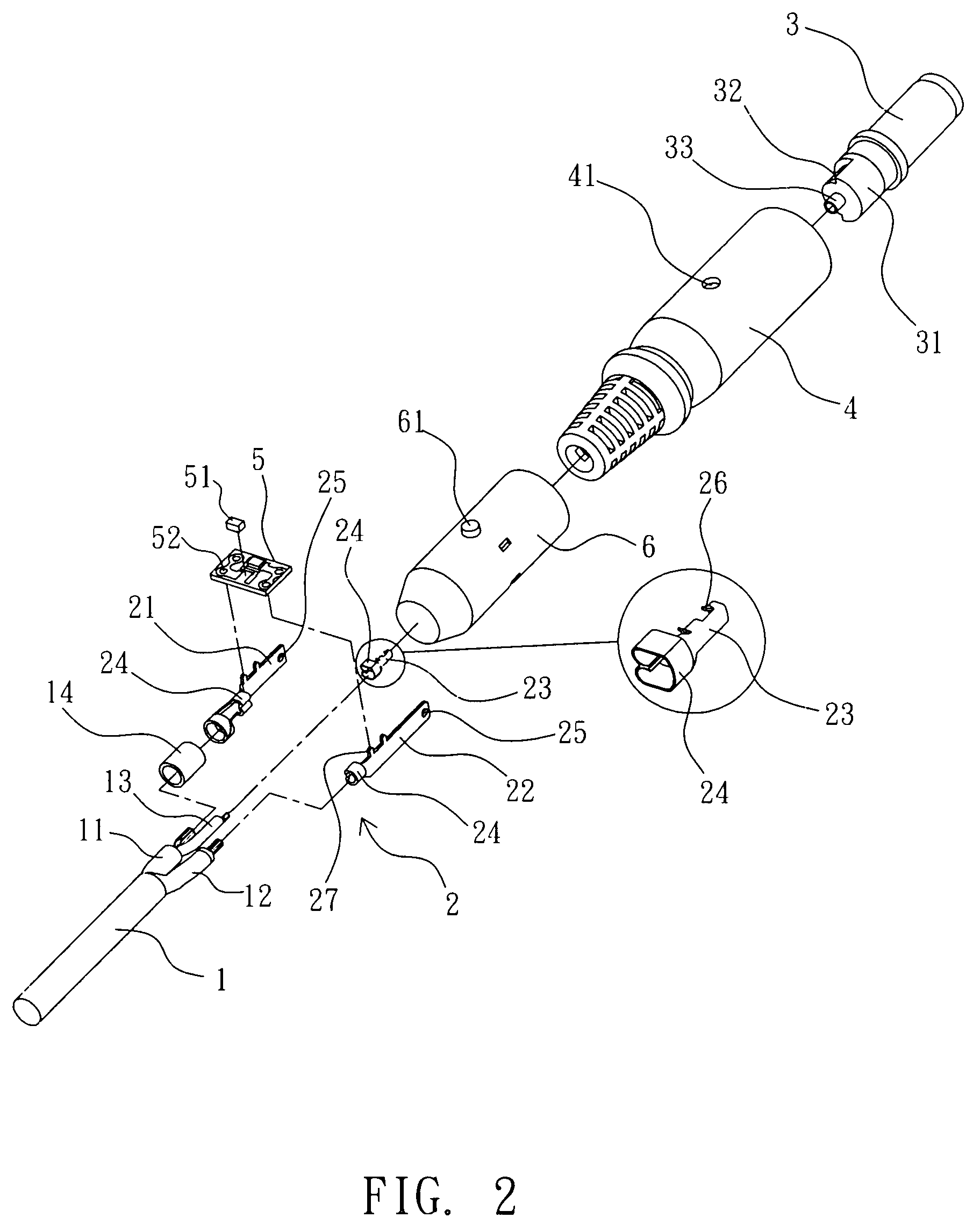
[0016]As shown from FIG. 2 to FIG. 7, the power plug assembly provided by the present invention is composed by a cable 1, a terminal set 2, a conductive sleeve tube 3 and an outer covering member 4.

[0017]The cable 1 has two power wires 11, 12 and a signal wire 13 can additionally be provided according to actual needs. End sections of the power wires 11, 12 and the signal wire 13 are provided with plural exposed conductive metal wires, e.g. copper wires, so the cable 1 is provided with positive and negative electricity and a function of signal transferring.

[0018]The terminal set 2 is formed by punching and bending metal sheets, such as copper sheets. The amount of terminals of the terminal set 2 is according to the amount of the wires mentioned above; as shown in FIG. 2, the terminal set 2 is composed by a positive terminal 21, a negative terminal 22 and a signal terminal 23. A connecting section 24 is respectively provided to each rear portion of the terminals, the connecting sectio...


PUM


Abstract

The present invention relates to a power plug assembly, comprises a cable having two power wires, end sections of each wire has plural conductive metal wires; a terminal set composed by a positive terminal and a negative terminal, a connecting section is respectively provided to the rear ends of the positive and the negative terminals and the connecting sections are respectively connected to plural conductive metal wires of end sections of the power wires, the surfaces of the positive and the negative terminals are provided with welding holes; a conductive sleeve tube having an inner tube and an outer tube, an insulating material is provided between the inner tube and the outer tube for insulation; after the two terminals are respectively provided on the outer tube and the inner tube of the conductive sleeve tube, a welding operation is processed and the welding material passes through the welding holes so the two terminals are connected and retained on the conductive sleeve tube; an outer covering member formed by a plastic injection molding and the rear portion of the conductive sleeve tube, the terminal set and the front portion of the cable are covered by the outer covering member via the plastic injection molding. With the improved connecting method of the cable, the terminal set and the conductive sleeve tube provided by the present invention, the connecting strength and the welding speed are increased, and the defective rate is lower and the quality can be ensured.

Description

FIELD OF THE INVENTION[0001]The present invention relates to a power plug assembly, more particularly to a power plug assembly in which a connecting fashion of cables and a conductive sleeve tube is improved and the connection is therefore enhanced.DESCRIPTION OF RELATED ART[0002]A power plug is commonly seen in our daily life. Categorized by functions, a power plug can be a power-receiving plug or a power-supplying plug, wherein the power-receiving plug is mostly an AC plug with two or three electrodes for receiving supplying power; the power-supplying plug is a DC plug having a shape like a round column, the diameter of the power-supplying plug is varied according to a diameter of power plug of an electronic goods, e.g. a note book computer or a cell phone.[0003]As shown in FIG. 1, which is a schematic view of a connection of a cable 10 of a conventional power-supplying plug and a conductive sleeve tube 20, the cable 10 includes two power wires 101, 102 respectively having positiv...

Claims


Application Information

Patent Timeline
Patent Type & Authority Patents(United States)
IPC IPC(8): H01R3/00
CPCH01R4/029H01R9/03H01R13/405H01R43/24
Inventor CHANG, HSING-WANG
Owner TAIWAN LINE TEK ELECTRONICS
Why Eureka
Try Eureka