Eureka AIR delivers breakthrough ideas for toughest innovation challenges, trusted by R&D personnel around the world.

Method for bonding plastic mold member onto metal housing

a metal housing and plastic mold technology, applied in the direction of adhesive processes, manufacturing tools, other domestic articles, etc., can solve problems such as affecting the yield enhancement

Inactive Publication Date: 2013-03-28
ICHIA TECH
View PDF10 Cites 23 Cited by
  • Summary
  • Abstract
  • Description
  • Claims
  • Application Information

AI Technical Summary

Benefits of technology

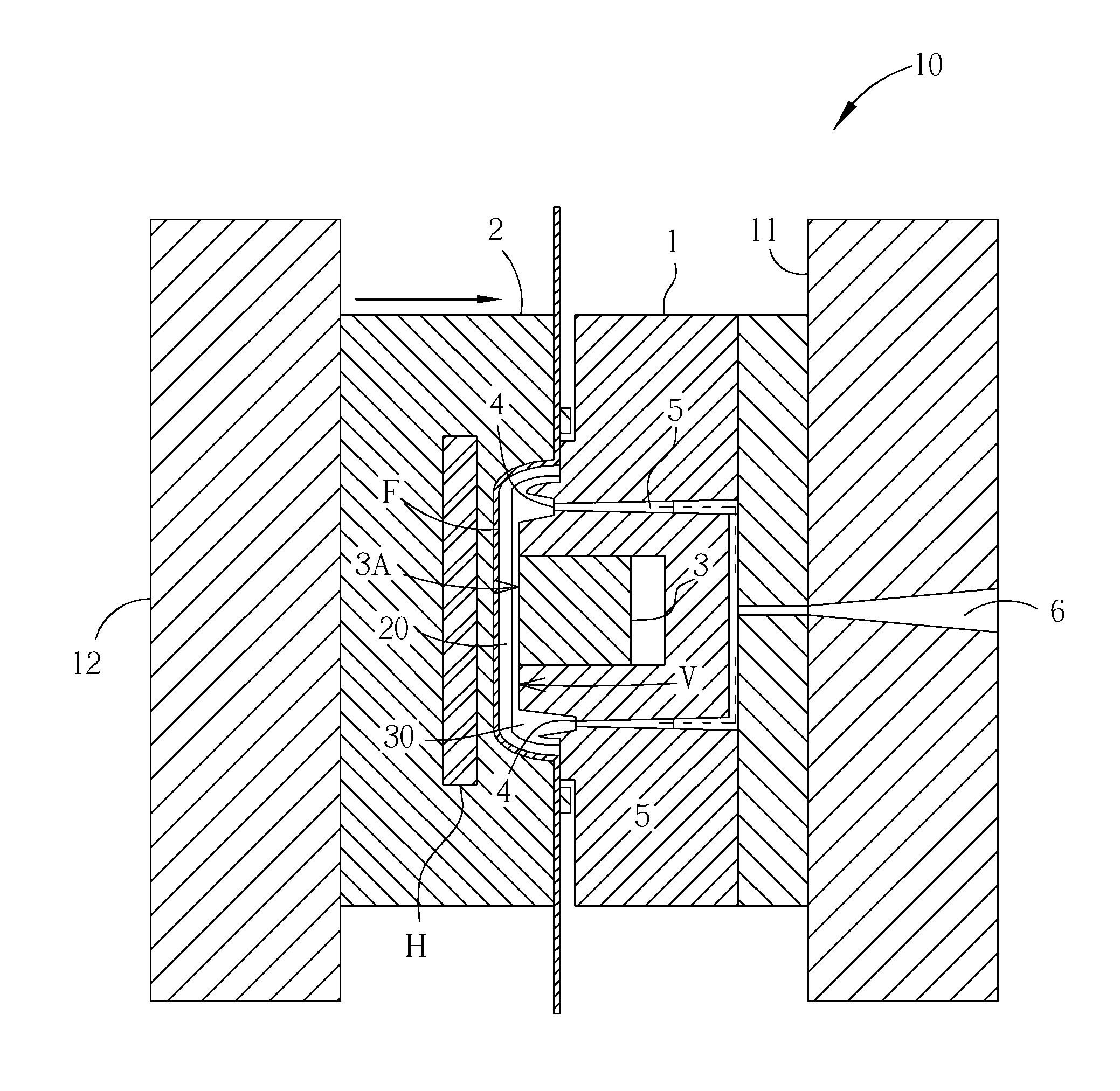
The present invention provides a method for improving metal-plastic composite bodies by overcoming shortcomings and disadvantages in prior art. This is achieved by using insert injection molding technology to form plastic mold members, logos, camera lenses, or fill flash light lenses directly onto a metal piece or metal housing. The method involves preparing the metal housing, forming an adhesive layer, performing a first injection molding to bond a plastic mold member, and performing a second injection molding to form an optical plastic member in the hollow-carved area. The technical effects include enhanced bonding strength and improved optical quality in the final composite body.

Problems solved by technology

It is very difficult for two curved surfaces to bond to each other, thereby hindering the yield enhancement.

Method used


Image

  • Method for bonding plastic mold member onto metal housing
  • Method for bonding plastic mold member onto metal housing
  • Method for bonding plastic mold member onto metal housing

Examples


Embodiment Construction

[0028]In the following detailed description of the invention, reference is made to the accompanying drawings which form a part hereof and wherein are shown, by way of illustration, specific embodiments in which the invention may be practiced. These embodiments are described in sufficient details to enable those skilled in the art to practice the invention. Other embodiments may be utilized; structural, logical, and electrical changes may be made without departing from the scope of the present invention.

[0029]Please refer to FIGS. 5 and 6, wherein FIG. 5 is a side view of a composite body with plastic members bonded to a metal housing, and FIG. 6 is a cross-sectional view of the composite body with plastic members bonded to metal housing of FIG. 5 taken along the line I-I′. The composite body with plastic members bonded to a metal housing may be a cell phone housing or a battery cover with hollow-carved logo (ex. characters or patterns) formed thereon for providing hidden backlight e...


PUM

PropertyMeasurementUnit
bonding areaaaaaaaaaaa
colorsaaaaaaaaaa
areaaaaaaaaaaa

Abstract

A method for bonding a plastic member onto a metal housing is provided. A metal housing having an inner surface and an outer surface is prepared. A hollow-carved area is provided on the metal housing. The inner surface of the metal housing is subjected to physical process, thereby forming a bonding area. An adhesive layer is formed on the bonding area. A plastic mold member is formed on the adhesive layer by performing a first plastic injection molding. An optical plastic member is molded on the hollow-carved area by performing a second plastic injection molding.

Description

BACKGROUND OF THE INVENTION[0001]1. Field of the Invention[0002]The present invention relates to a method for fabricating a metal-plastic composite body, and more particularly, to a fabricating method using insert injection molding technology to form plastic mold members, light-guiding pattern of logos, camera lens, or fill (flash) light lens directly on a metal piece or a metal housing.[0003]2. Description of the Prior Art[0004]In recent years, metal housings with lightweight and high rigidity properties have become more and more necessary since the portable electronic products are developed to be lighter, shorter and smaller. In order to follow such requirements, the technology for composite materials that combines metal housing with plastic mold members has become a main focus in the industry. The conventional method for fabricating the above-mentioned composite article may comprise the steps of molding the metal piece and the plastic piece separately, applying an adhesive on the...

Claims


Application Information

Patent Timeline
Patent Type & Authority Applications(United States)
IPC IPC(8): B29D11/00B21D22/00B23K10/00B24C1/04B23K26/38B29C45/14B29L9/00
CPCB29C45/14311B24C1/06B29C45/1671B29C45/14B29D11/00C09J5/02
Inventor CHANG, YU-CHIHYU, SHIH-PULIU, CHANG-LI
Owner ICHIA TECH
Why Eureka
Eureka Blog
Learn More