Roller skate with removable boot

a roller skate and boot technology, applied in the field of roller skates with removable boot, can solve the problems of affecting the stability of the boot, and the lack of longitudinal play in the locking, etc., and achieves the effects of simple, robust, and easy opening

Inactive Publication Date: 2001-08-07
SKIS ROSSIGNOL
View PDF16 Cites 16 Cited by
  • Summary
  • Abstract
  • Description
  • Claims
  • Application Information

AI Technical Summary

Benefits of technology

is to produce a simple, robust, very stable automatic binding which is free of play and easy to open in order to release the boot.
According to one embodiment, the catching and locking element which is common to the four catching points has nibs which engage over the bars or tenons via inclined sides so as to press them into the bottom of the V-shaped notches. A further effect of these inclined sides is that they take up any play which is due to wear of the notches and / or of the bars or tenons.
Unequal wear of the two sides of the chassis can be compensated for by the fact that the catching and locking element is made in the form of two parallel plates with cutouts joined together by a spacer piece with play which allows longitudinal movement of one plate with respect to the other.

Problems solved by technology

An embodiment of this kind does, however, present a number of drawbacks: it is not easy to engage the slideways of the boot over the rails, especially as no play can be tolerated, and this demands a manufacturing precision or a force-fitting which are hardly acceptable or alternatively demands elastic deformation which detracts from the stability of the boot.
The absence of longitudinal play in the locking is also difficult to master.
Releasing the boot is somewhat inconvenient.

Method used


Image

  • Roller skate with removable boot
  • Roller skate with removable boot
  • Roller skate with removable boot

Examples


first embodiment

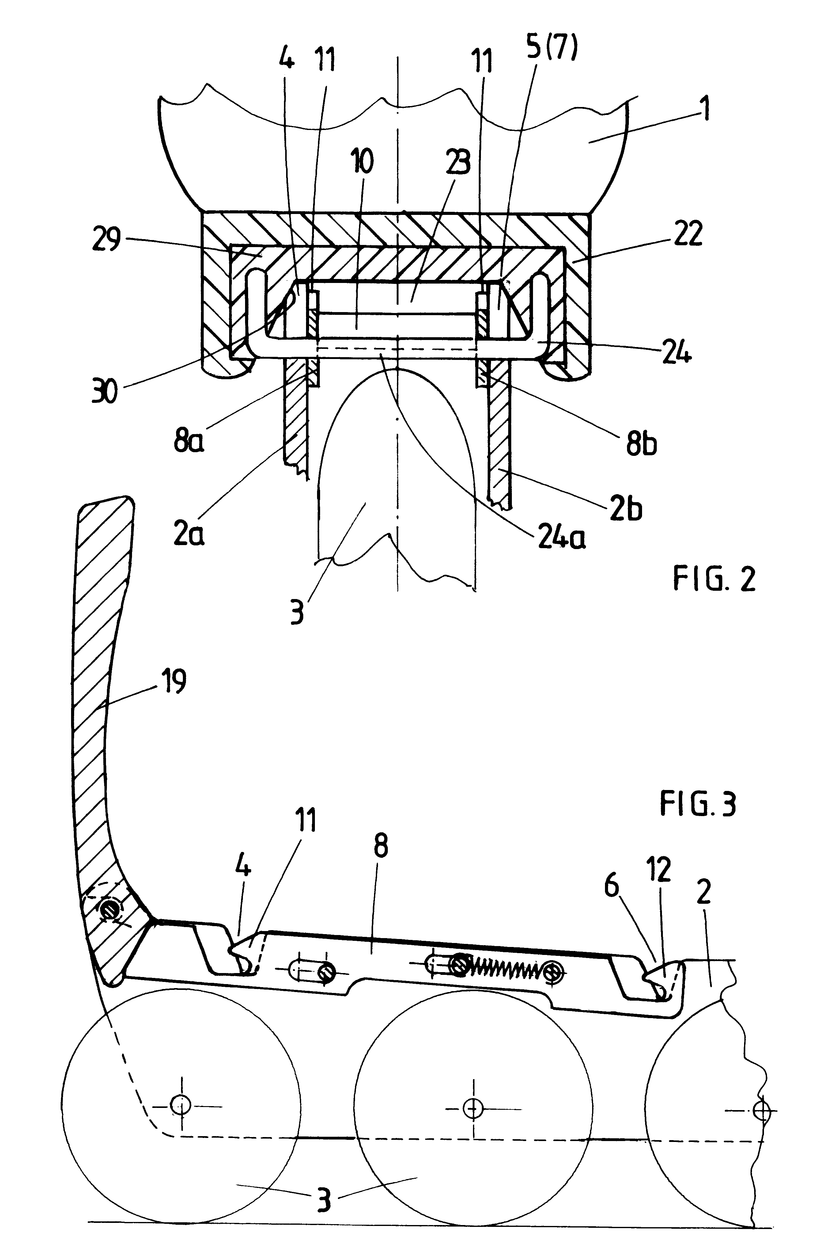
In the alternative form depicted in FIG. 4, the parallel plates 8a and 8b constituting the latch lie on the outside of the chassis, against the outer faces of the walls 2a and 2b of the chassis. As in the first embodiment, the plates 2a and 2b are connected by a spacer piece 10 which passes this time through the walls 2a and 2b of the chassis through two slots which allow the latch to move. The plates 8a and 8b are also guided by shoulders 31 which extend over at least part of the length of the chassis.

The catching pieces secured to the chassis consist of C-shaped metal components 32 embedded in the inserts 29. The two ends of the component 32 form two tenons 33, 34 which engage in the notches 4 to 7 of the chassis and in the latch. These tenons 33 and 34 do not project or project very little into the chassis, which means that space for rollers or for housing a brake becomes free.

The plates 8a and 8b of the latch could just as well be guided, on the one hand, from below, by bearing ...

second embodiment

A second embodiment will now be described with reference to FIGS. 8 to 10.

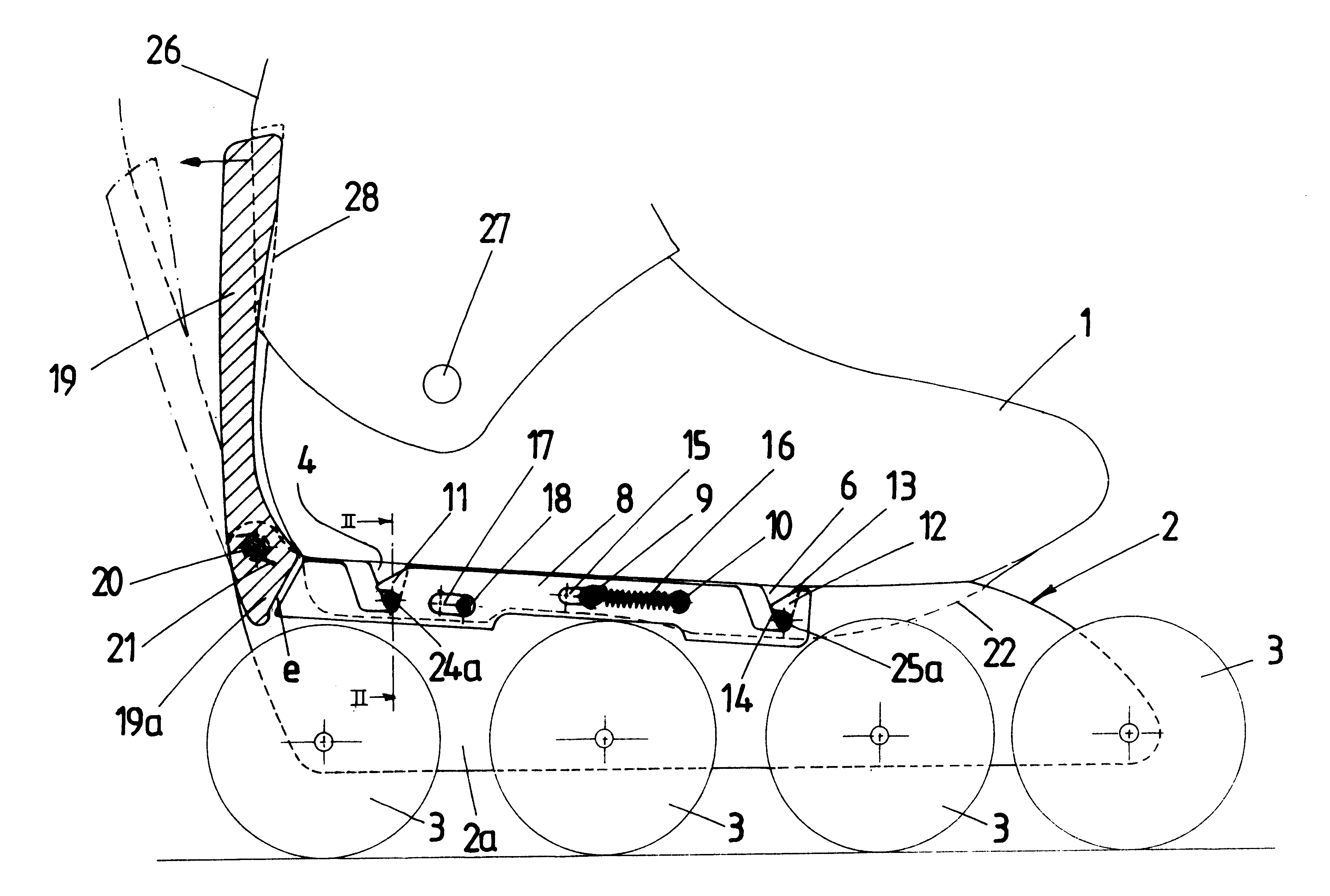
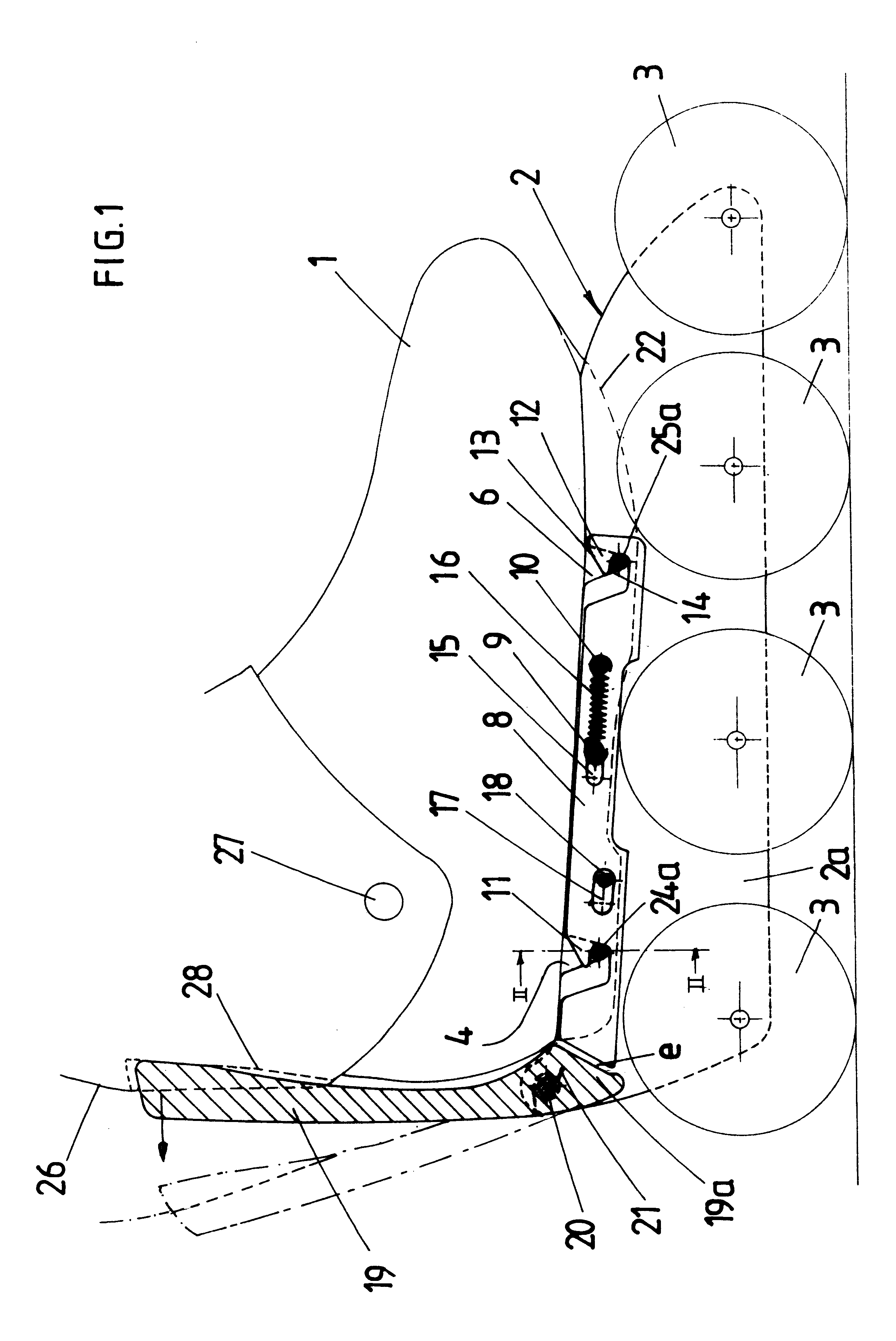
In order to avoid a multiplying of reference numerals, the chassis 2 and the unlocking lever 19 have been denoted by the same reference numerals as were used in the first embodiment, despite the differences in shape which may be observed. The same is true of the V-shaped notches 4 and 6.

This embodiment also comprises a catching and locking element common to the four catching points. This catching element consists of two parallel rods 40 which will hereafter be referred to by the expression latch for reasons of simplicity. This latch 40 is mounted so that it can slide longitudinally in the chassis 2, in which it is guided between, on the one hand, two spacer pieces 41 and 42 of the chassis and, on the other hand, three crossmembers 43, 44, 49 of this same chassis. The latch 40 is equipped with two hooks 45 and 46 which are intended to retain and lock the tenons 24a and 25a of the boot. The rear end of the latch...

third embodiment

The third embodiment depicted in FIGS. 14 to 16 can be distinguished from the previous embodiments by the presence of distinct catching and locking elements or latches for attaching the front tenons and attaching the rear tenons of the boot.

As depicted diagrammatically in FIG. 14, catching and locking is achieved by two latches 61 and 62 working in opposite directions. These latches are produced in identical ways, which means that a detailed description of just the latch 61 will be given, remembering that this latch may consist of a single piece or of two identical pieces, one for each tenon of the boot, for example. The latch 61 is in the shape of a .GAMMA. articulated to the chassis about an axle 63 and the upper part of which forms a nib 64. This latch has a lateral post 65 which engages in a notch 66 of a catch 68 forming a lever of the first kind which, at its fulcrum, has a cylindrical cutout 69 via which this lever rests against a cylindrical boss 76 of the chassis 2 which ac...


PUM


Abstract

Roller skate comprising a chassis (2) equipped with rollers (3) and a boot (1) attached removably to the chassis at four points by catching and locking. Catching and locking are achieved automatically and simultaneously at all of the attachment points using a common element (8) subject to the action of an elastic means (16). Unlocking is achieved using a lever (19) articulated to the rear of the chassis and which can be used as a handle when putting the chassis on.

Description

The subject of the present invention is a roller skate comprising a chassis equipped with rollers and a boot attached removably to the chassis at four non-aligned points, by catching and locking so as to provide a stable connection between the boot and the chassis, locking being achieved automatically by the deformation of an elastic member when the roller chassis is put on.PRIOR ARTThe removable attachment of a boot to an ice skate or roller skate goes back to the beginnings of skating. Attachment was generally achieved using claws actuated by a lever and which gripped onto the sole of the boot. Such bindings are described in patent CH 118 742 and patent U.S. Pat. No. 1,402,010.In a more modern version, described in patent U.S. Pat. No. 3,918,729, the sole of the boot is equipped with a metal plate which, at the front, has two holes in the shape of keyholes which catch on two tenons of the skate and, at the rear, a bayonet hole in which there engages a rotary member which has an ac...

Claims


Application Information

Patent Timeline
Patent Type & Authority Patents(United States)
IPC IPC(8): A63C17/00A63C17/06A63C17/20A63C17/04
CPCA63C17/06A63C17/20A63C2017/0053
Inventor GIGNOUX, PIERRE
Owner SKIS ROSSIGNOL
Why Eureka
Try Eureka