Cargo latch

a technology for latches and cargo, applied in the field of cargo latches, can solve the problems of not being able to hold freight containers securely in their final storage position, taking rather harsh measures, and non-functional latches

Inactive Publication Date: 2001-08-07
TELAIR INTERNATIONAL GMBH
View PDF17 Cites 52 Cited by
  • Summary
  • Abstract
  • Description
  • Claims
  • Application Information

AI Technical Summary

Problems solved by technology

This sort of jamming delays loading and unloading of the cargo space and, because the operating personnel are under time pressure during these processes, often makes them take rather harsh measures in order to store the containers as quickly as possible.
The use of force not uncommonly damages the latch in ways so subtle that they are not noticed at first but later, as a result of the severe vibration during flight, can make the latch nonfunctional.
If several latches are so damaged, there is a risk that during the flight the freight container will no longer be held securely in its final storage position.
Furthermore, because of the deflecting roller it is possible to reduce the maintenance frequency of the cargo latch without making it less reliable.

Method used


Image

  • Cargo latch
  • Cargo latch
  • Cargo latch

Examples


Embodiment Construction

In the following description, the same reference numerals are used for identical components, or parts and components with identical actions.

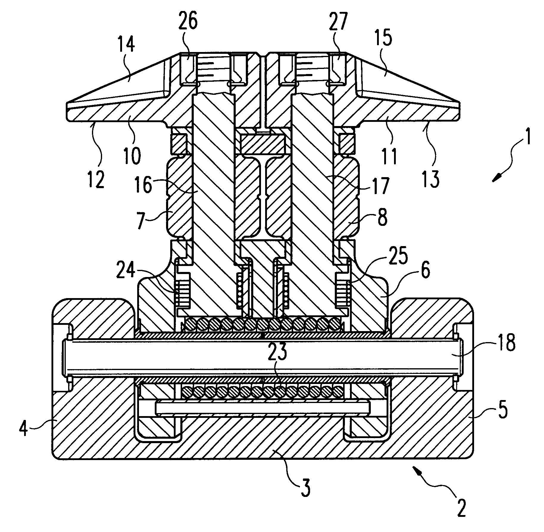
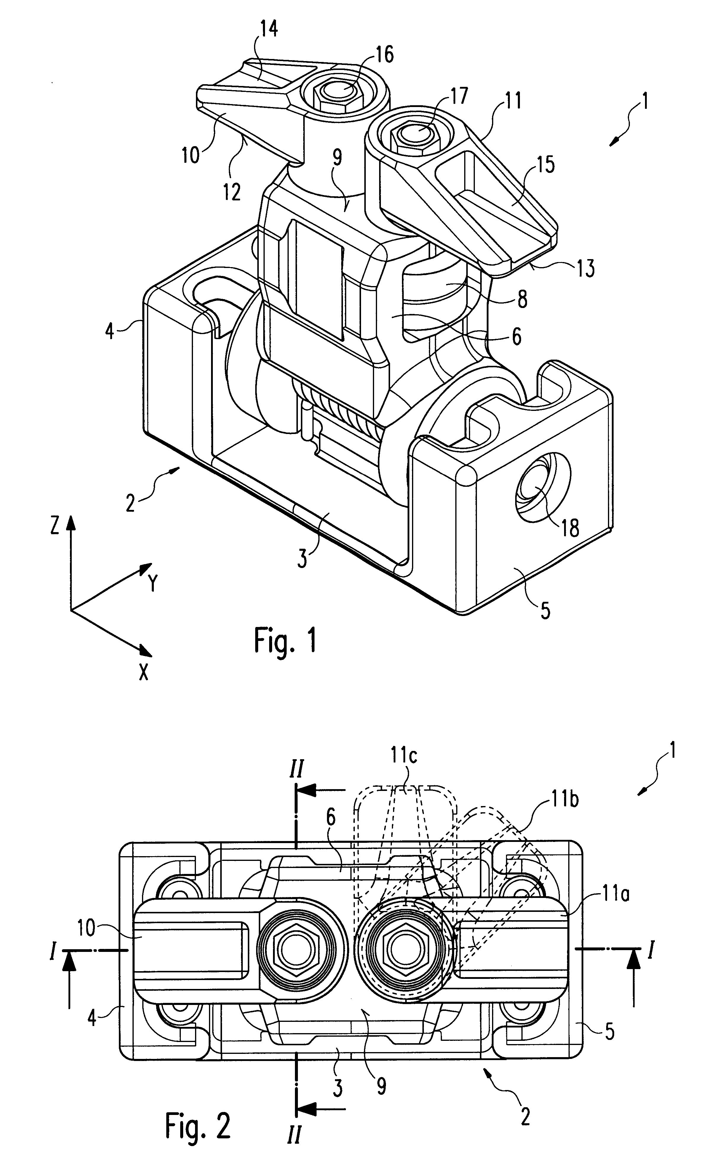
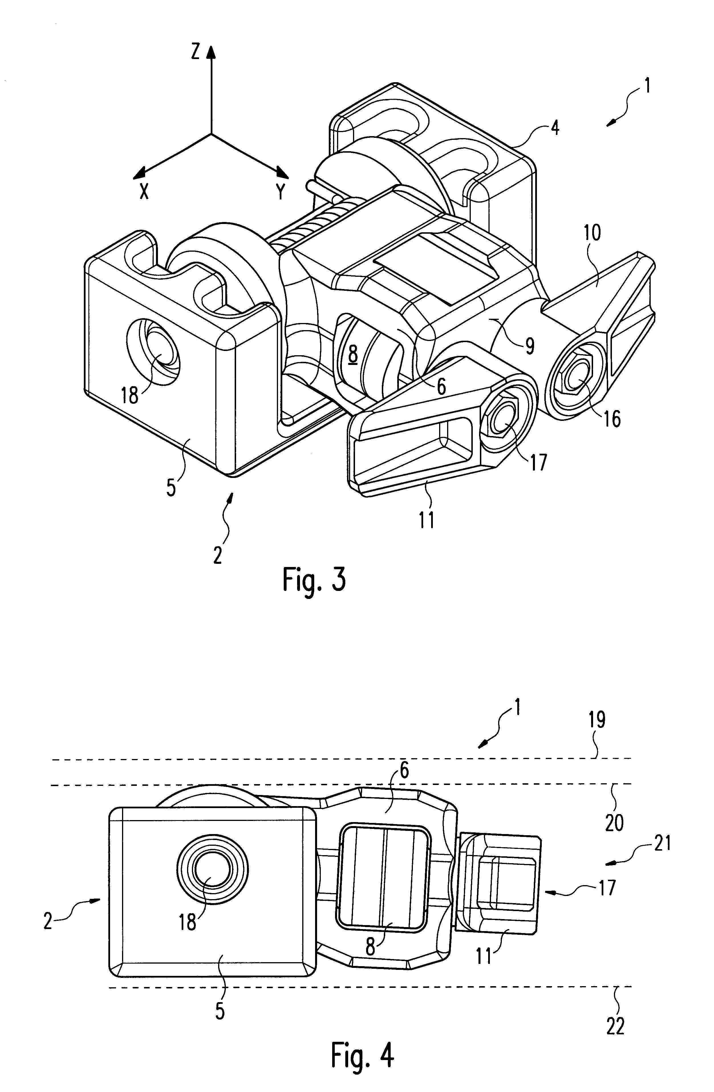
In FIGS. 1, 5 and 6 a cargo latch in accordance with the invention, with a U-shaped frame 2 and a base 6 that can be pivoted within the frame 2, is shown in its operating or restraining position. Above a covering surface 9 of the base 6 are disposed a first restraining hook 10 and a second restraining hook 11, each of which can be rotated parallel to the covering surface 9 of the base 6. The U-shaped frame 2 comprises a bottom portion 3, a first side part 4 and a second side part 5. Mounted in the first side part 4 and the second side part 5 respectively are the first and second ends of a first shaft 18. Within the U-shaped opening of the frame 2 is situated a lower end of the base 6, which encloses the shaft 18 and which is mounted on the shaft 18 in the manner of a connecting rod in order that it can be pivoted with respect to the frame 2. The...


PUM


Abstract

A cargo latch is provided for use in restraining objects such as containers, pallets and the like, against movement with respect to a floor of a cargo hold, in particular the cargo hold of an aircraft. The latch comprises a frame with a shaft disposed therein and a base, a lower end of which is rotatably mounted on the shaft. The base can therefore pivot with respect to the frame. At least one restraining hook is pivotally mounted to an upper end of the base.

Description

The present invention relates to a cargo latch for use in restraining objects such as containers, pallets and the like, against movement with respect to a floor of a cargo hold, in particular the cargo hold of an aircraft.DESCRIPTION OF THE PRIOR ARTTo secure containers, pallets and the like in particular to the floor of a cargo hold in an aircraft, latches are known that comprise a frame and at least one latch hook or restraining hook.The latch described in U.S. Pat. No. 5,265,991 comprises a frame to attach the latch to the floor of the cargo hold and a base pivotably mounted on the frame. The base comprises at its end away from the frame two hooked lugs pointing away from one another, which are integrally joined to the base and can be pivoted therewith. The arrangement of frame, base and hooked lug formed together with the base is so constructed that the hooked lug overlaps and rests on a holding strip of a freight container when the latter is in its final storage position, secur...

Claims


Application Information

Patent Timeline
Patent Type & Authority Patents(United States)
IPC IPC(8): B60P7/06B60P7/13
CPCB60P7/13
Inventor HUBER, THOMASHOLZNER, RICHARD
Owner TELAIR INTERNATIONAL GMBH
Why Eureka
Try Eureka