
Pattern recognition

a pattern recognition and pattern technology, applied in the field of pattern recognition devices, can solve the problems of difficult application of multi-layer perceptions to real problems such as speech recognition, performance non-, and inability to learn such seemingly simple functions as exclusive-or functions

Inactive Publication Date: 2001-08-07
BRITISH TELECOMM PLC
View PDF16 Cites 38 Cited by
  • Summary
  • Abstract
  • Description
  • Claims
  • Application Information

AI Technical Summary

Problems solved by technology

The main disadvantage of these is their inability to perform non-linear mappings from the input space to the output space, so that they cannot learn such apparently simple functions as the exclusive-or function.
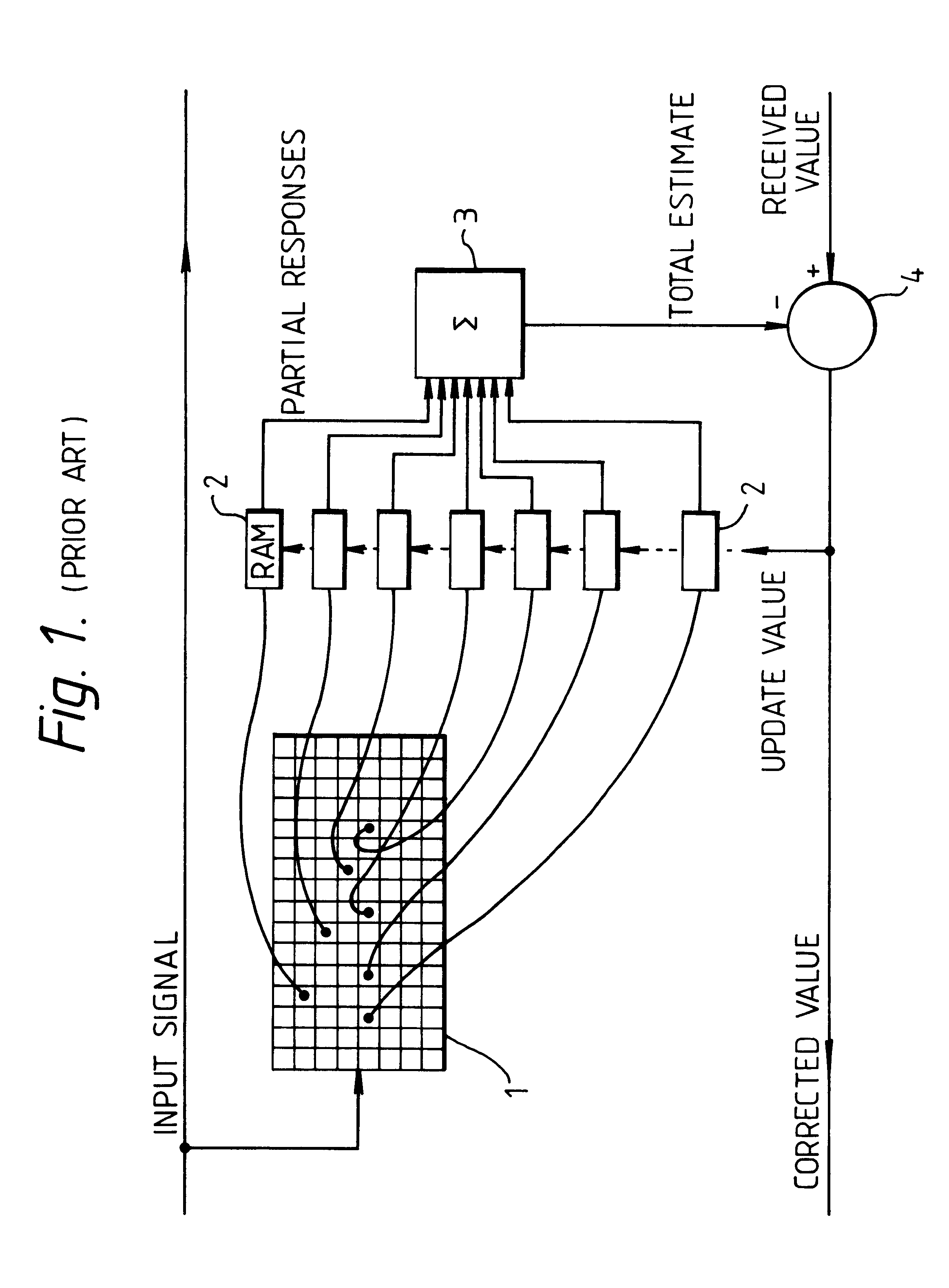
A solution to this problem is the multi-level percepton, where the output of a first layer of perceptrons supplies the input to a second layer; however, large amounts of training are required in order to learn quite simple non-linear mappings (i.e. convergence is slow), and this has made the application of multi-layer perceptions to real problems such as speech recognition very difficult.
It is of course conventional to employ binary coding to represent digital values of a signal, but (as discussed in "Guide to pattern and recognition using random-access memories"- Aleksander and Stonham, computers and digital techniques, February 1979, Vol 2 No 1, Page 36 "6.3 coding of physical data") this is not particularly suitable for this class of pattern recognition devices since signal values which are quite close in signal space are disproportionately far apart in Hamming distance.
The authors there propose a Gray code (which employs the same number of bits as the binary code) to overcome this problem but note that this can lead to spurious results as widely differing input signal levels can be close in Hamming distance.
It is, however, very inefficient and can require a large amount of input space; for example, for input data having 256 levels (i.e. the typical output of an 8 bit digital to analog converter), a 256 bit wide input buffer is required--which is clearly impractical (the binary and Gray code versions require only 8 bits, of course).

Method used


Image

  • Pattern recognition
  • Pattern recognition
  • Pattern recognition

Examples


Embodiment Construction

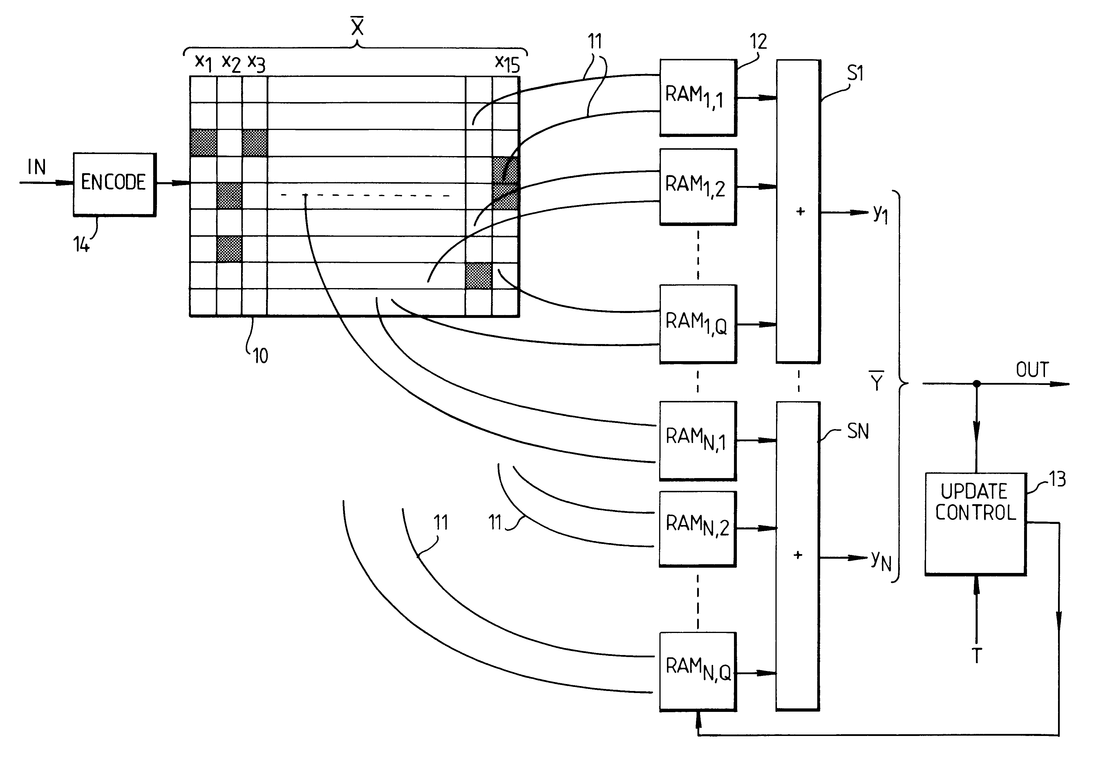
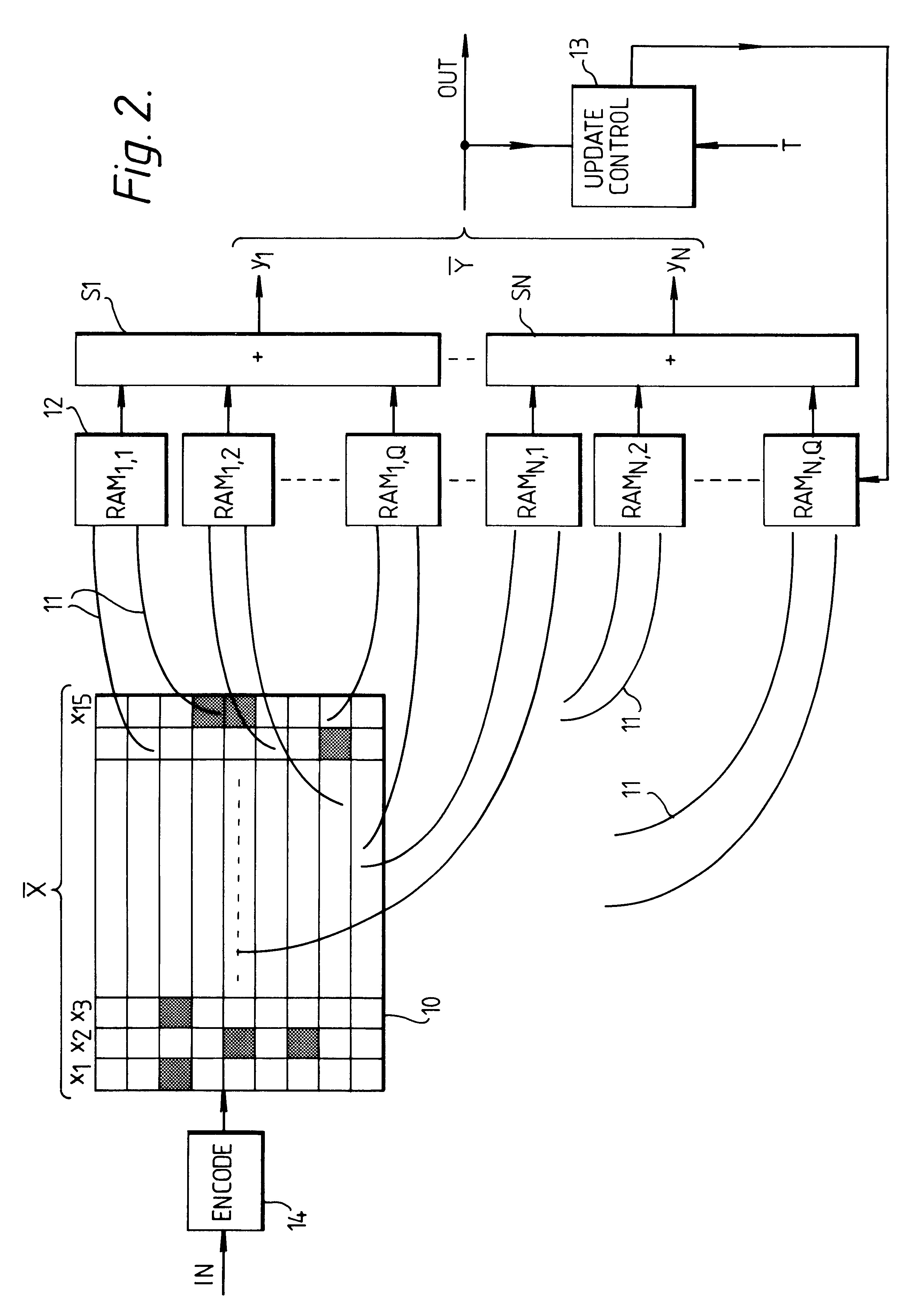
Referring to FIG. 2 there is shown a pattern recognition device having an input for receiving a time-varying signal in the form of digital samples. These are divided into frames of (for example) sixteen samples x.sub.1 . . . x.sub.15 (or, in vector notation, X) and stored in a store 10. To avoid confusion, it may be stated that a frame may be regarded as a sixteen element vector (viz. a one-dimensional array or pattern of samples) representing a point in a notional 16-dimensional input space.

Note that the case of a one-dimensional array is by way of example; multi-dimensional arrays (e.g. for image recognition) are equally possible.

Although, in the example, the input is a one-dimensional array, it is convenient to view the store 10 as two-dimensional since it must accommodate a number of bits for each sample. N-tuple connection lines 11 are, as in FIG. 2, connected to the store to form address lines for several banks 12 of memories. The connections are distributed over the bits of t...


PUM


Abstract

Input values are digitally represented and the bits used to address memories. A composite (e.g. the sum) of the memory outputs is formed, and update control is used during "learning" to modify the memory contents. The digital representation is formed by an encoder which encodes input values using a redundant code, which preferably has a Hamming distance to signal distance relationship which has a relatively steep initial slope and is closer to being monotonic than is the relationship for a simply binary code.

Description

1. Field of the InventionThe present invention is concerned with pattern recognition devices.2. Related ArtPattern recognition devices commonly receive, in digital form, an input pattern of bits which is then processed to produce a scalar value, or a number of such values, which are regarded as a vector. These may then be subjected to a thresholding operation to provide an output indicating the nature of an unknown pattern supplied to the device. Many such devices are learning devices, in that they are not constructed to recognize particular patterns but are, before use, supplied with training patterns, the output of the device being compared with information as to the nature of the pattern, or identifying a class to which it belongs, and the comparison result used as feedback to vary parameters stored within the device.It is convenient to view such systems in terms of an input space and an output space. For example, one which receives a set of five scalar values and produces two sc...

Claims


Application Information

Patent Timeline
Patent Type & Authority Patents(United States)
IPC IPC(8): G06K9/62H04B3/23
CPCH04B3/231G06K9/6217G06F18/21
Inventor TATTERSALL, GRAHAM D
Owner BRITISH TELECOMM PLC
Learn More