Voltage controlled oscillator with accelerating and decelerating circuits

a voltage control and oscillator technology, applied in the direction of logic circuits, multiple-port active networks, electric pulse generators, etc., can solve the problems of increasing the difficulty of providing noise and jitter free clock signals, differential control voltage systems are more complex to design and fine tune than single-ended systems, and differential systems tend to consume more power

Inactive Publication Date: 2001-08-21
ARM LTD
View PDF1 Cites 9 Cited by
  • Summary
  • Abstract
  • Description
  • Claims
  • Application Information

AI Technical Summary

Problems solved by technology

As digital integrated circuits scale down in size and increase in speed it becomes increasingly difficult to provide noise and jitter free clock signals.
Differential control voltage systems are more complex to design and fine tune than single ended systems.
Differential systems also tend to consume more power due to the additional and larger circuitry they contain and have more failure mechanisms.
A problem with such systems is that the voltage-to-current FET conducts substantially zero current until the input control signal passes a threshold level and at the other end of the voltage range saturation effects degrade the linear response.
This limits the control voltage range, particularly as long channel FETs are used that tend to have higher threshold voltages.
The problem of a reduced control voltage range due to threshold voltage effects can also occur differential systems.

Method used


Image

  • Voltage controlled oscillator with accelerating and decelerating circuits
  • Voltage controlled oscillator with accelerating and decelerating circuits
  • Voltage controlled oscillator with accelerating and decelerating circuits

Examples


Embodiment Construction

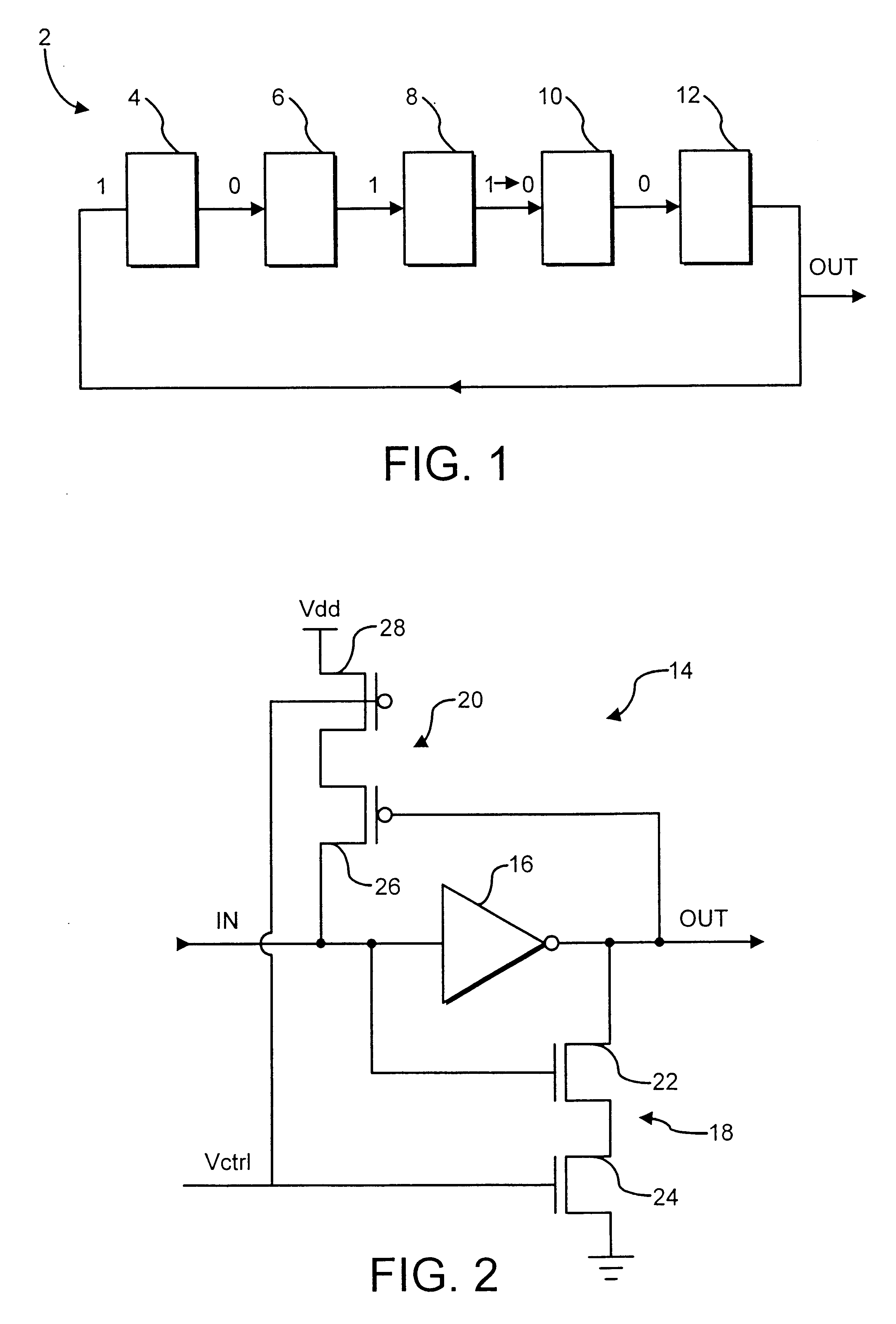
FIG. 1 schematically illustrates a ring oscillator 2 having five oscillator stages 4, 6, 8, 10 and 12. The oscillator stages 4, 6, 8, 10 and 12 are arranged in a ring with the output of oscillator stage 12 being coupled to the input of oscillator stage 4. In this example each oscillator stage 4, 6, 8, 10 and 12 acts as an invertor serving to invert the signal presented to its input to generate its output. If the input to an oscillator stage 4, 6, 8, 10 and 12 changes, then the oscillator stage output signal will also change after a propagation delay time that is characteristic of the oscillator stage. Since the ring oscillator 2 has an odd number of oscillator stages 4, 6, 8, 10 and 12 with each stage being an invertor, there is no stable static set of oscillator stage output signals and instead a change of signal circulates around the ring oscillator 2. At the instant illustrated in FIG. 1, the input signal to oscillator stage 8 can be considered to have just changed to become a "1...


PUM


Abstract

A voltage controlled oscillator is provided in the form of two ring oscillators 30 and 32. Each oscillator stage 14 includes an invertor 16, a level change accelerating circuit 18 and a level change decelerating circuit 20. The level change accelerating circuit 18 is responsive to an input control signal Vctrl to increase the oscillator frequency by decreasing the propagation delay through the invertor 16. The level change decelerating circuit 20 is responsive to the input control signal Vctrl to decrease the oscillator frequency by increasing the propagation delay through the invertor 16. Pairs of opposing invertors 34, 36, 38, 40 and 42 disposed between output signal lines of corresponding oscillator stages 14 in the two ring oscillators 30 and 32 serve to lock the two ring oscillators in antiphase.

Description

1. Field of the InventionThis invention relates to the field of voltage controlled oscillators. More particularly, but not exclusively, this invention relates to voltage controlled oscillators of a type suitable for use in generating clock signals used to drive digital circuits.2. Description of the Prior ArtAs digital integrated circuits scale down in size and increase in speed it becomes increasingly difficult to provide noise and jitter free clock signals. Phase locked loop systems including voltage controlled oscillators are often used in the synthesis of clock signals in digital systems. Voltage controlled oscillators generate an output signal with a frequency that is dependent upon an input control signal. The input control signal is a particularly sensitive node within the system as it is typically left floating for a large proportion of the time and so small noise voltages can produce large frequency shifts, e.g. a one Volt change in the input control voltage might produce a...

Claims


Application Information

Patent Timeline
Patent Type & Authority Patents(United States)
IPC IPC(8): H03K3/354H03K3/00H03K3/03
CPCH03K3/354H03K3/0315
Inventor SCHORN, ERIC BERNARD
Owner ARM LTD
Why Eureka
Try Eureka