
Super-regenerative transceiver with improved frequency discrimination

a transceiver and frequency discrimination technology, applied in the field of wireless communication transmitters, wireless communication receivers, electronic oscillator designs, systems, can solve the problems of unfriendly 15-50 mw batteries and far too much to operate for long on small batteries, so as to improve the sensitivity or data rate improve the sensitivity of receiver signals or transmission rates, and expand the receiver frequency range of operation

Active Publication Date: 2019-12-12
MUMEC INC
View PDF6 Cites 2 Cited by
  • Summary
  • Abstract
  • Description
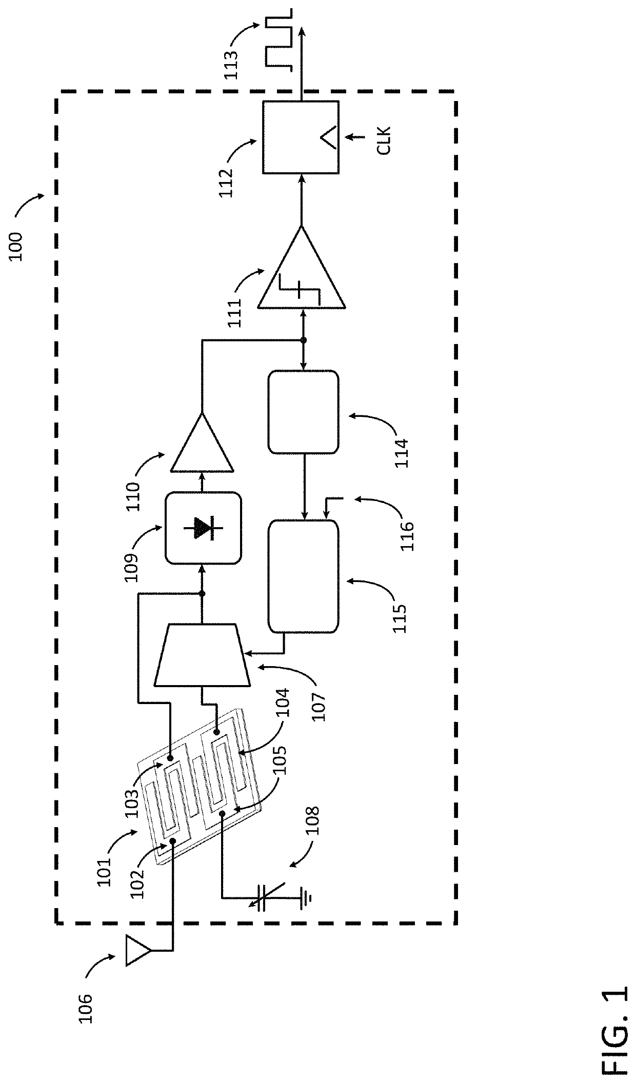
  • Claims
  • Application Information

AI Technical Summary

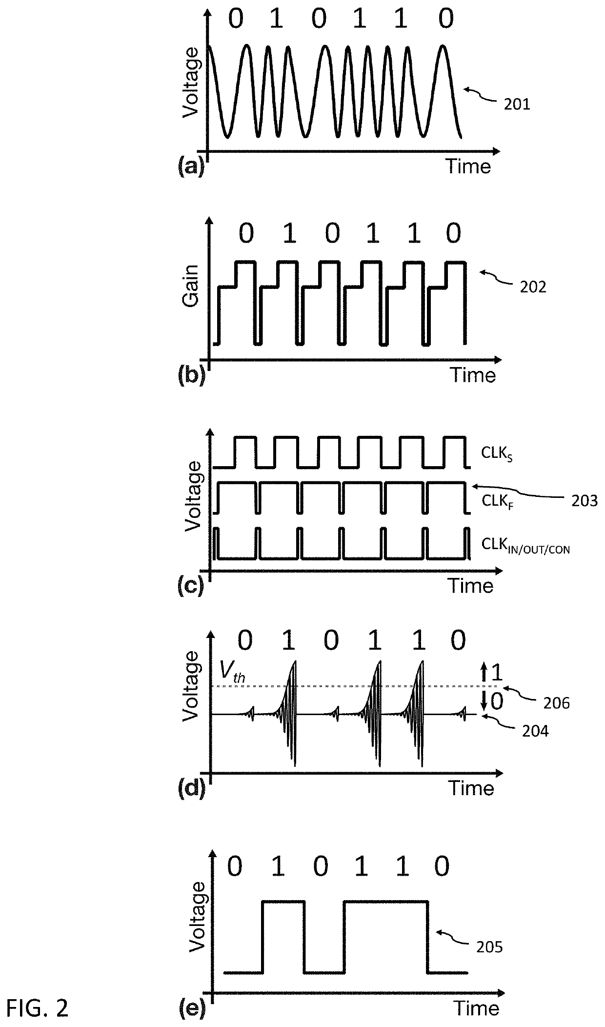
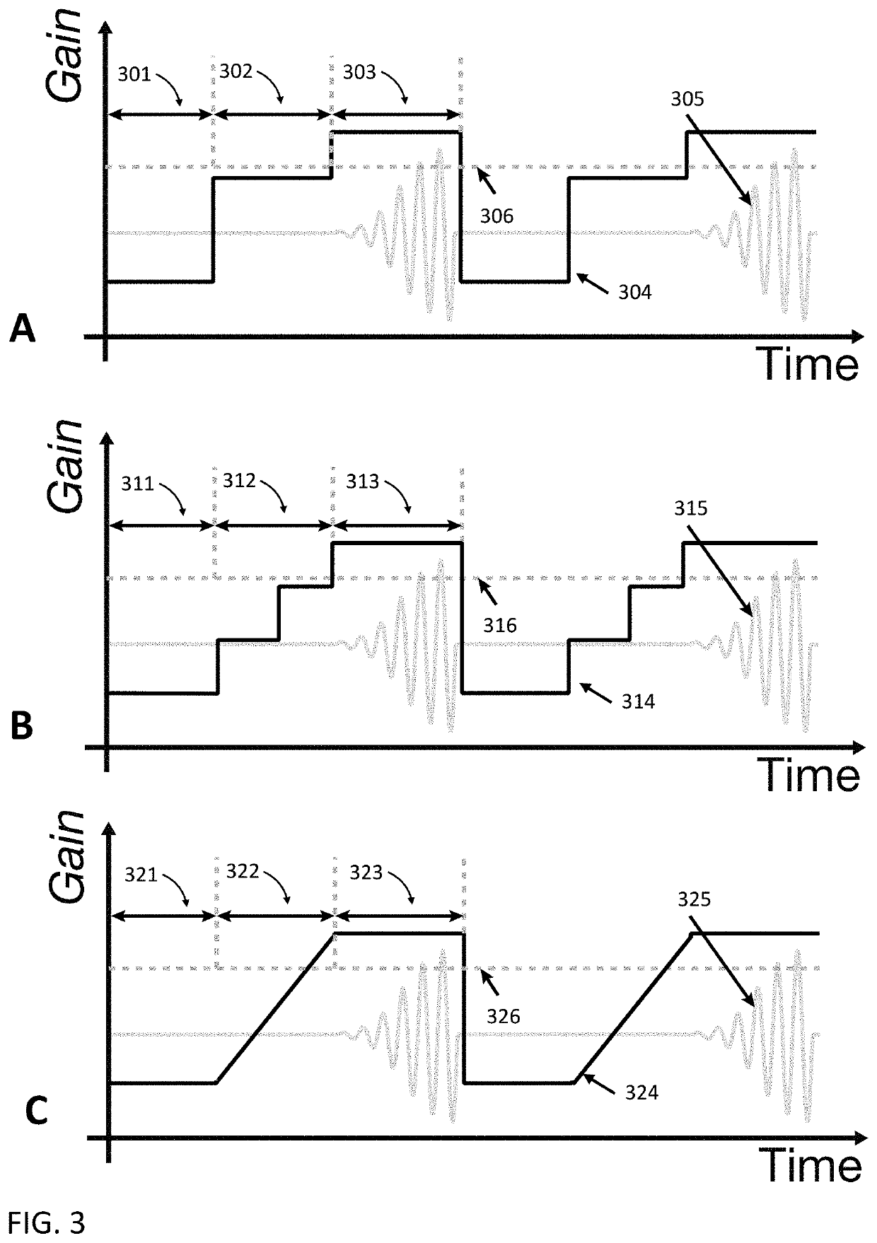
Benefits of technology

[0008]Bluetooth, Bluetooth Low-Energy (BLE) and Z-Wave are protocols widely used in home and commercial automation as well as consumer wireless applications. Focused on low data-rates of 9.6 kbps to 40 kbps at 900 MHz, Z-Wave offers radio technology with both increased range when compared with 2.4 GHz protocols such as Zigbee, as well as simpler RF hardware and standards compliance. Indeed, the simple frequency-shift keying modulation and reasonable specs allows such transceivers to be implemented with little difficulty for use in home and industrial monitoring applications. The Bluetooth and BLE standards offer greater compatibility and more operating modes for a wide variety of consumer and other commercial applications, at the cost of somewhat increased complexity. Though designed for battery operated remote devices, current implementations of these standards typically consume a battery-unfriendly 15-50 mW or more, clearly far too much to operate for long on the small batteries needed to deploy the low-cost sensor motes envisioned in future ubiquitous IoT systems.
[0009]Power consumption remains an important consideration in the design of wireless transceivers. With the increase in the number of such transceivers used both for Internet of Things (IoT) applications, as well as consumer electronics, the desire for lower power operation is highly commercially relevant. By reducing component part count, and simplifying data communication complexity, power consumption may be lowered. In some embodiments of this disclosure, a radio frequency (RF) resonator is embedded in an active, controllable positive feedback loop to form a tunable RF channel-selecting radio transceiver employing a super-regenerative reception scheme. In some embodiments, in radios employing super-regenerative reception schemes, an amplifier combined in closed-loop feedback super-regeneratively amplifies input signal on resonance, allowing detection of weak radio signals without the need for complex, power-hungry architectures. In some embodiments, the resulting transceiver utilizes the high Q-factor (500-200,000) and tunable frequency capabilities of some resonators (e.g., MEMS-based resonators) to enable direct selection of a single narrow RF channel in a broader band, as desired for low-power operation.
[0011]The disclosed receivers, transmitters, and transceivers are well suited to wireless sensor node applications, where low-power consumption and reliability are critical. In some embodiments, controllable frequency tuning also allows the same device to operate as a frequency-shift keyed transmitter, or with simple switching of the output, an on-off keying transmitter, making a complete transceiver in one exceedingly simple device. In some embodiments, the geometric flexibility of resonator structure design permits a large range of usable RF frequencies, from 60 MHz VHF and lower frequencies, all the way up to UHF or above. For example, a bank of resonators, each designed for a particular range of frequencies, may be coupled by a switch network to one or more receiver antennas, and one or more feedback elements with optional one or more tuning elements, and optional one or more response sensing elements to create a receiver that may span a broad range of frequencies.
[0012]Embodiments of the present disclosure are directed to devices, systems, and methods of capturing symbol data from a wireless signal using an RF receiver having a resonator and a feedback element with variable gain. Implementations are directed to using the feedback element gain to control the frequency response of the resonator to improve receiver signal sensitivity or receiver data rates. Additional implementations are directed to tuning the resonator resonance frequency and expanding the receiver frequency range of operation using multiple resonators.

Problems solved by technology

Though designed for battery operated remote devices, current implementations of these standards typically consume a battery-unfriendly 15-50 mW or more, clearly far too much to operate for long on the small batteries needed to deploy the low-cost sensor motes envisioned in future ubiquitous IoT systems.

Method used


Image

  • Super-regenerative transceiver with improved frequency discrimination
  • Super-regenerative transceiver with improved frequency discrimination
  • Super-regenerative transceiver with improved frequency discrimination

Examples


embodiment 1

2. The RF receiver of embodiment 1, wherein the feedback element comprises a controlled impedance element.

3. An RF receiver as in any one of embodiments 1-2, wherein the two or more electrodes comprise at least two feedback electrodes, and the controlled impedance element is coupled differentially to the at least two feedback electrodes.

4. An RF receiver as in any one of embodiments 1-3, wherein at least one of the one or more feedback control signals controls at least one of the at least one feedback electrode to couple to a dissipative element during at least a portion of the period of a single symbol.

5. The RF receiver of embodiment 1, wherein the two or more electrodes comprise at least two feedback electrodes, the feedback element comprises a closed-loop feedback element, and the closed-loop feedback element is coupled to the at least two feedback electrodes.

embodiment 5

6. The RF receiver of embodiment 5, wherein the resonator comprises four or more electrodes, the four or more electrodes comprise at least four feedback electrodes, and the closed-loop feedback element is coupled differentially to the at least four feedback electrodes.

7. The RF receiver of embodiment 5, wherein at least one of the one or more feedback control signals controls at least one of the at least two feedback electrodes to couple to a dissipative element during at least a portion of the period of a single symbol.

8. The RF receiver of embodiment 5, wherein at least one of the one or more feedback control signals controls at least two of the at least two feedback electrodes to couple to each other via a dissipative element to each other during at least a portion of the period of a single symbol.

9. An RF receiver as in any one of embodiments 1-8, further comprising:

a tuning element coupled to at least one tuning electrode, wherein the two or more electrodes comprise the at leas...

embodiment 9

10. The RF receiver of embodiment 9, wherein the tuning element comprises one or more capacitors, at least one of the one or more frequency control signals controls an output capacitance of the tuning element, and the resonance frequency is based at least in part upon the output capacitance of the tuning element.

11. The RF receiver of embodiment 9, wherein the tuning element comprises a voltage source, at least one of the one or more frequency control signals controls an output voltage of the tuning element, and the resonance frequency is based at least in part upon the output voltage of the tuning element.

12. An RF receiver as in any one of embodiments 9-11, wherein at least one of the one or more frequency control signals is based at least in part upon a temperature associated with the resonator.

13. An RF receiver as in any one of embodiments 9-12, wherein at least one of the at least one feedback electrode and at least one of the at least one tuning electrode are coupled to a fir...


PUM


Abstract

The present disclosure provides a super-regenerative transceiver with a feedback element having a controllable gain. The super-regenerative transceiver utilizes the controllable gain to improve RF signal data sensitivity and improve RF signal data capture rates. Super-regenerative transceivers described herein permit signal data capture over a broad range of frequencies and for a range of communication protocols. Super-regenerative transceivers described herein are tunable, consume very little power for operation and maintenance, and permit long term operation even when powered by very small power sources (e.g., coin batteries).

Description

CROSS-REFERENCE TO RELATED APPLICATION[0001]This application claims the benefit of priority to U.S. Provisional Patent Application No. 62 / 457,823, filed on Feb. 11, 2017, and U.S. Provisional Patent Application No. 62 / 457,825, filed on Feb. 11, 2017, each of which are hereby incorporated by reference in their entirety, including all descriptions, references, figures, and claims for all purposes.STATEMENT REGARDING FEDERALLY SPONSORED RESEARCH OR DEVELOPMENT[0002]This invention was made with government support under Award Nos. (FAIN) 1549465 and 1738563 awarded by National Science Foundation. The government has certain rights in the invention.BACKGROUNDField of the Disclosure[0003]The disclosure relates generally to wireless communication receivers, wireless communication transmitters, and electronic oscillator designs, systems, methods, and devices. Particularly, the disclosure relates to designs, systems, methods and devices for realizing improvements to super-regenerative resonato...

Claims


Application Information

Patent Timeline
Patent Type & Authority Applications(United States)
IPC IPC(8): H04B1/16H03H9/02H03H3/02H03B5/32H03H9/24
CPCH04B1/16H03H9/02259H03H2003/027H03H3/02H03H9/02228H03H9/02393H03H9/2447H03B5/323H03B5/1215H03B5/30H03D11/04H03D11/08H03D2200/0074H04L27/127H03B5/32H04B1/24H04W64/006H03H9/2457
Inventor NAING, THURA LINROCHELEAU, TRISTAN ORION
Owner MUMEC INC
Learn More