Magnetic clamp for welding magnetic objects

a magnetic object and clamping technology, applied in the field of magnetic clamps, can solve the problems of having to adjust the length of the bolt into the "v" of the clamping device, and achieve the effect of increasing the holding power and facilitating the twisted off of the pip

Inactive Publication Date: 2001-08-28
LEON JR RAYMOND
View PDF6 Cites 85 Cited by
  • Summary
  • Abstract
  • Description
  • Claims
  • Application Information

AI Technical Summary

Benefits of technology

The present invention is directed to a magnetic clamp having two cooperating magnetic members for use in arc welding a magnetic workpiece object. The present invention is particularly useful when welding pipes since a single flat magnet does not stay on a pipe very

Problems solved by technology

If the two magnets are rigidly at an angle to each other, a problem arises in that the

Method used


Image

  • Magnetic clamp for welding magnetic objects
  • Magnetic clamp for welding magnetic objects
  • Magnetic clamp for welding magnetic objects

Examples


second embodiment

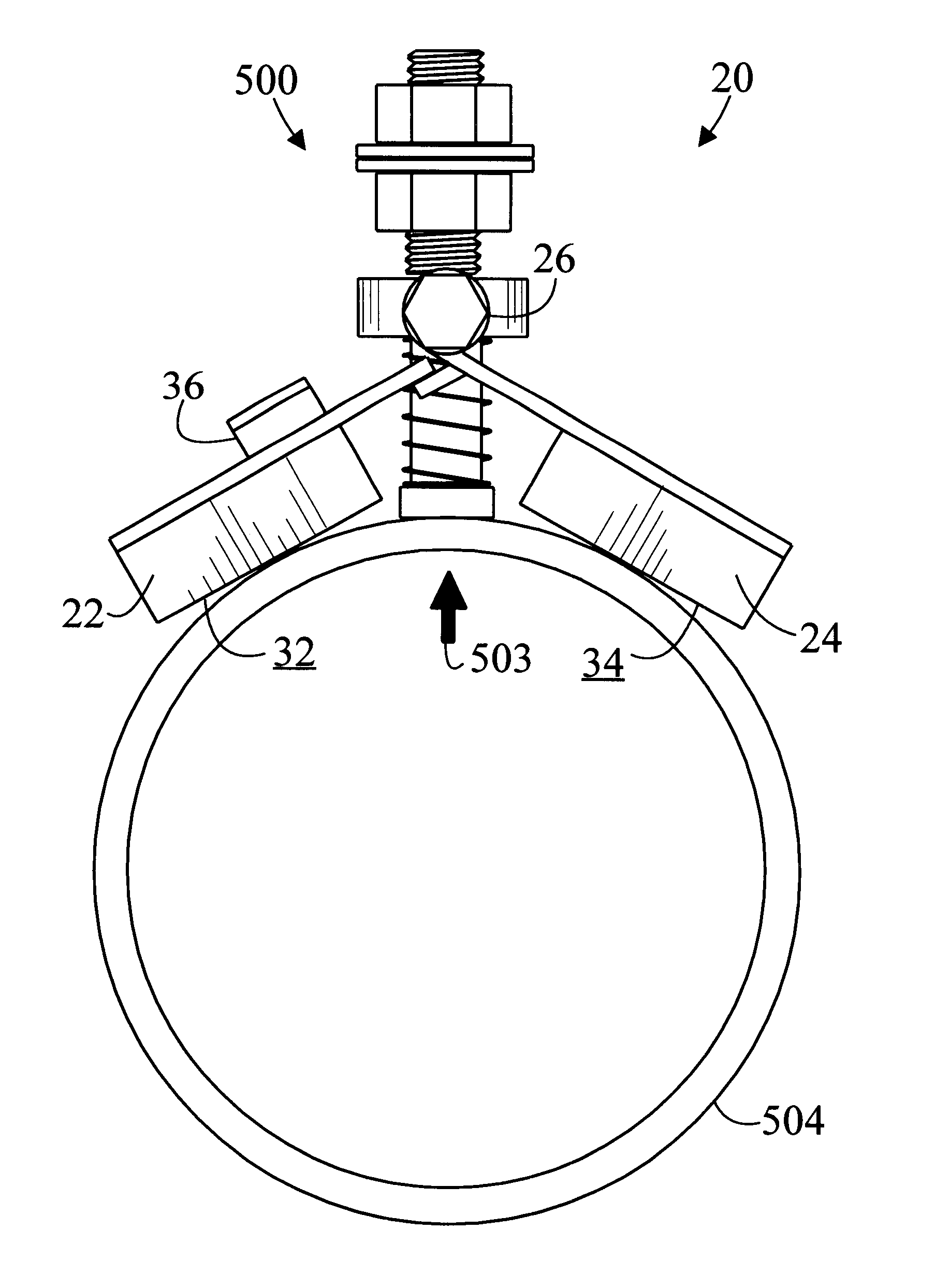
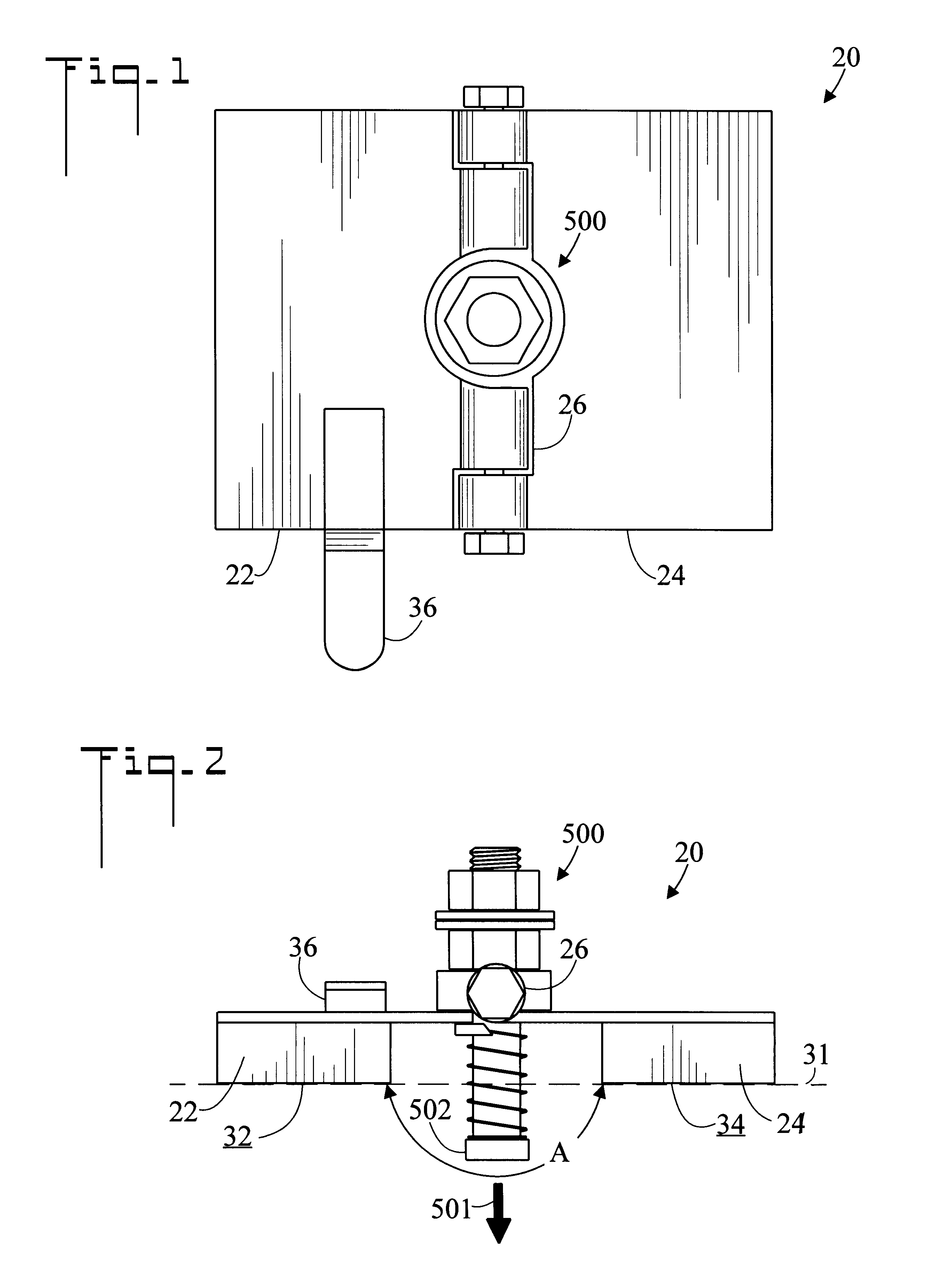
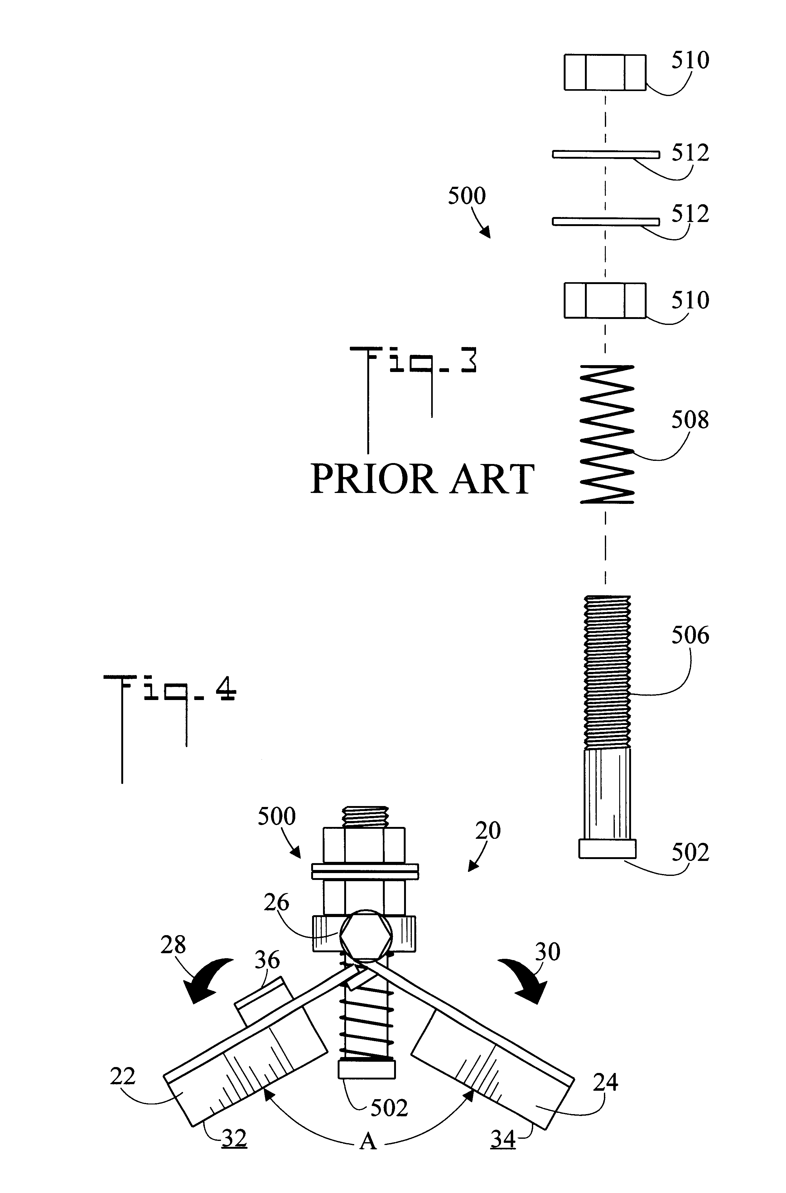
Referring to FIGS. 7-10, there are illustrated top plan, end elevation, bottom plan, and installed end elevation views respectively of the magnetic clamp, generally designated as 120. Similar to clamp 20, clamp 120 includes a first magnetic member 122, a cooperating second magnetic member 124, and a spring loaded terminal 500 disposed between the two. Two hinges 126 connect first magnetic member 122 and second magnetic member 124. A central portion 125 is disposed between the two hinges 126, and spring loaded terminal 500 is connected to central portion 125. A tapered stop 127 is connected to central portion 125. Stop 127 prevents first 122 and second 124 magnetic members from abutting spring loaded terminal 500. In FIG. 10, clamp 120 has been installed on pipe 504 with first magnetic member 122 and second magnetic member 124 rotated in directions 128 and 130 respectively to abut pipe 504. Contact end 502 of spring loaded terminal 500 has been urged in direction 503.

third embodiment

Referring to FIGS. 11-13, there are illustrated top plan, end elevation, and installed end elevation views respectively of the magnetic clamp, generally designated as 220. Clamp 220 includes a first magnetic member 222, and a second magnetic member 224 connected to first magnetic member 222 so that first 222 and second 224 magnetic members form an angle A therebetween. A spring loaded terminal 500 having a contact end 502 is disposed between first magnet member 222 and second magnetic member 224. In FIG. 13, magnetic clamp 220 is attached to magnetic object 504 wherein first magnetic member 222, second magnetic member 224, and contact end 502 all abut magnetic object 504. Removal tab 236 is connected to first magnetic member 222, second magnetic member 224, or junction 240 between the two magnetic members.

It is noted that in all embodiments of the present invention, spring loaded terminal 500 does not contact the magnetic members. This is so that current does not flow through the ma...


PUM


Abstract

A magnetic clamp (20) for welding a magnetic object (504), includes a first magnetic member (22) and a second magnetic member (24). A hinge (26) connects magnetic members (22) and (24) so that an angle formed by magnetic members (22) and (24) may be changed. A spring loaded terminal (500) having a contact end (502) is disposed between first magnetic member (22) and second magnetic member (24). Magnetic clamp (20) may be attached to magnetic object (504) so that first magnetic member (22), second magnetic member (24), and contact end (502) all abut magnetic object (504). In a preferred embodiment, a removal tab (36) is connected to magnetic clamp (20) to assist in removing magnetic clamp (20) from magnetic object (504).

Description

The present invention pertains generally to welding, and in particular to a magnetic welding clamp that is attached to magnetic objects to provide a ground during arc welding.When arc welding, it is necessary to attach a ground to the object being welded while the other pole of the electric circuit is the welding rod. When the electricity passes through the welding rod to the object, it melts the tip of the welding rod thereby depositing molten metal on the object.Usually a spring clamp is used to connect the ground cable from the welding apparatus to the object. Nuts on the top of the clamps are used to attach the lug of the ground cable to the clamps. In one common embodiment, a spring loaded terminal (refer to FIG. 3) is attached to a flat magnetic clamp. The spring loaded terminal has a bolt that passes through the middle of the magnet and abuts the object to be welded. In this fashion, the electric current does not pass through the magnet, but rather is shunted directly through...

Claims


Application Information

Patent Timeline
IPC IPC(8): B25B11/00B23K37/04
CPCB23K37/0435B25B11/002B23K2201/06Y10S269/902Y10S269/901B23K2101/06
Inventor LEON, JR., RAYMOND
Owner LEON JR RAYMOND
Why Eureka
Try Eureka