System and method for monitoring water content or other dielectric influences in a medium

a dielectric influence and sensor technology, applied in the direction of resistance/reactance/impedence, instruments, nuclear engineering, etc., can solve the problems of affecting the accuracy of measurement, limiting the length over which water content can be measured, and weakening of pulses

Inactive Publication Date: 2001-08-28
BATTELLE ENERGY ALLIANCE LLC +1
View PDF4 Cites 115 Cited by
  • Summary
  • Abstract
  • Description
  • Claims
  • Application Information

AI Technical Summary

Benefits of technology

The sensor system described in this patent allows for non-contact, full-width measurements of materials like paper and food without damaging them. It can also track changes in humidity levels during production processes with high accuracy. Additionally, it can record the precise locations and orientations where readings are taken, allowing for better mapping of overall product quality.

Problems solved by technology

The technical problem addressed in this patent text needs to be identified by a senior R&D person who has read it through.

Method used


Image

  • System and method for monitoring water content or other dielectric influences in a medium
  • System and method for monitoring water content or other dielectric influences in a medium
  • System and method for monitoring water content or other dielectric influences in a medium

Examples


example 2

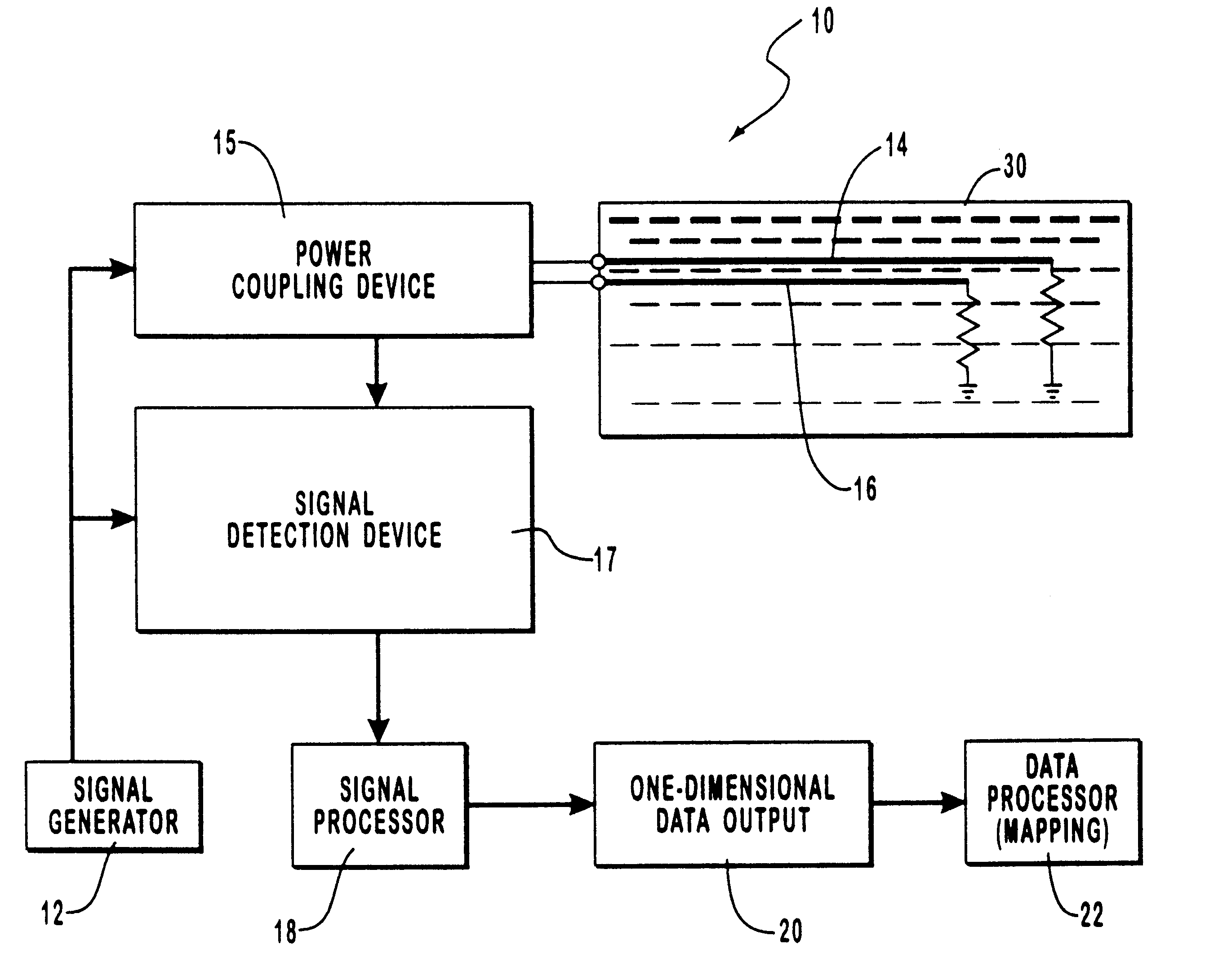
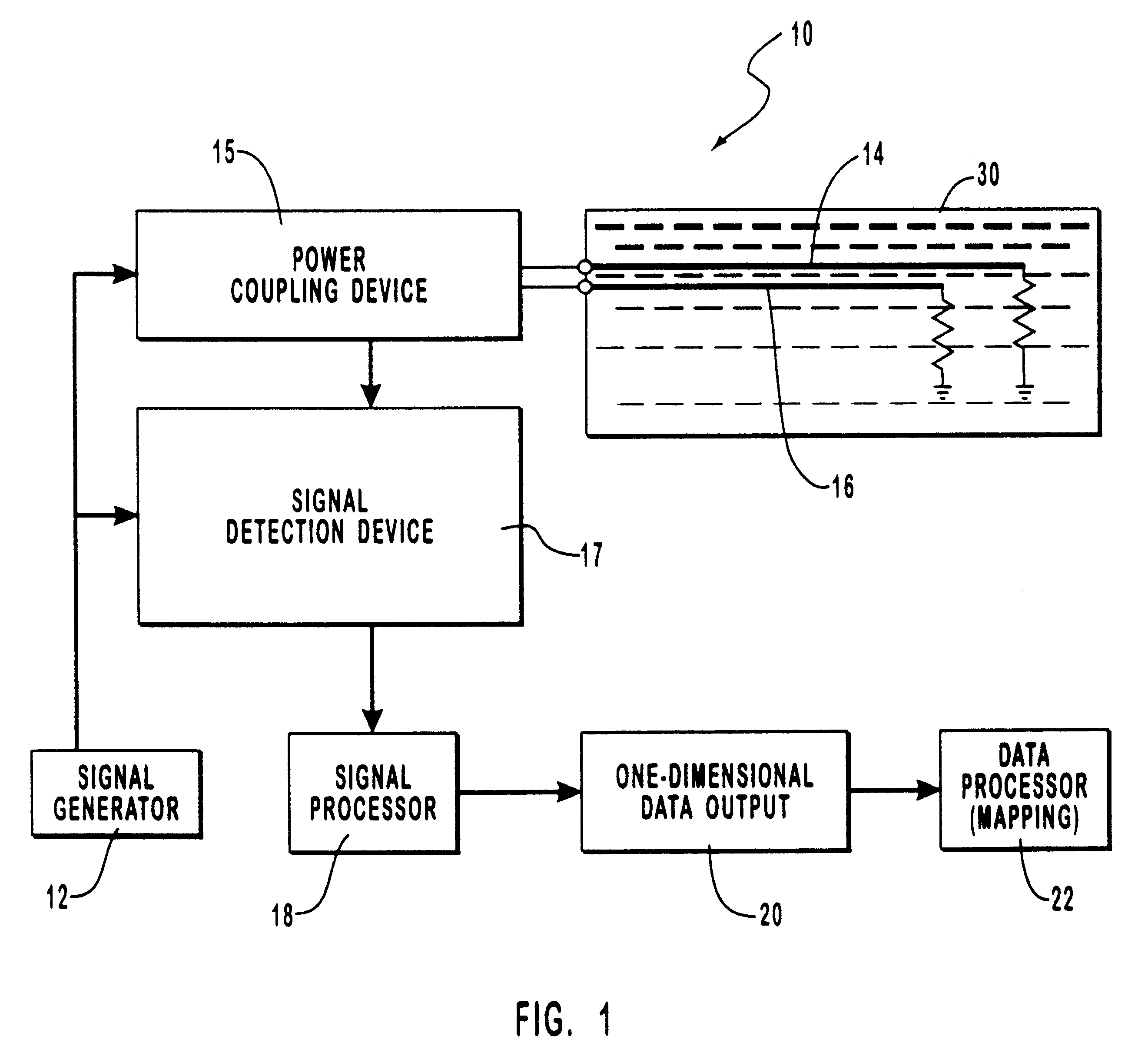
A sensor system was constructed including two slotted coaxial cables attached to a microwave generator and a laboratory network analyzer. The cables were buried in a twenty foot long trough of compost material simulating a biofilter application. When operated, the sensor system readily detected changes in water content of 0.05 g water / g soil. Changes on the order of 0.1 g / g are significant in biofilters, so good sensitivity was shown.

example 3

A sensor system was constructed comprising slotted coaxial cable lines 10 feet long attached to a microwave generator and a laboratory network analyzer. The slotted cable lines included a transmit line and a receive line that were one inch apart, and each line terminated with 50 ohms, which was the same impedance as the cable lines. The slotted cable lines were laid in a plastic tray and immersed in compost which had been air dried in room air and at room temperature for over two weeks. At 96.5 inches down the slotted cable lines and away from the network analyzer, an approximate 15 inch section of compost was removed and mixed with enough water to make a 15% by weight water content. This water / compost mixture was then added back to the section of compost where originally removed. Reference data at the starting time was then taken, with subsequent data taken at time periods of 18 hours, 42 hours, and 60 hours after the reference data. The boundaries of the region of compost with add...

example 4

A sensor system was constructed as described above in Example 3. The slotted cable lines were laid in a plastic tray and immersed in compost which had been air dried in room air and at room temperature for over two weeks. At 96.5 inches down the slotted cable lines and away from the network analyzer, an approximate 15 inch section of compost was removed and mixed with enough water to make a 6% by weight water content. This water / compost mixture was then added back to the section of compost where originally removed. Reference data at the starting time was then taken, with subsequent data taken at time periods of 4 hours, 8 hours, and 16 hours after the reference data. The signal frequency was swept from 1 MHz to 1000 MHz with 401 frequency points, and 10 dBm (10 mW) of power was applied.

FIG. 4 is a graph of the data collected during the above time periods depicting signal propagation time in relation to signal magnitude. The time shown is round trip time of propagation of the signal ...


PUM


Abstract

A sensor system is provided that measures water content or other detectable properties in a medium along the entire length of the sensor at any point in time. The sensor system includes an electromagnetic signal generator and a transmission line disposed in a medium to be monitored. Alternatively, the transmission line can be configured for movement across a medium to be monitored, or the transmission line can be fixed relative to a moving medium being monitored. A signal is transmitted along the transmission line at predetermined frequencies, and the signal is returned back along the transmission line and/or into an optional receive line in proximity to the transmission line. The returned signal is processed to generate a one-dimensional data output profile that is a function of a detectable property of the medium. The data output profile can be mapped onto a physical system to generate a two-dimensional or three-dimensional profile if desired. The sensor system is useful in a variety of different applications such as agriculture, horticulture, biofiltration systems for industrial offgases, leak detection in landfills or drum storage facilities at buried waste sites, and in many other applications.

Description


Claims


Application Information

Patent Timeline
Owner BATTELLE ENERGY ALLIANCE LLC
Why Eureka
Try Eureka