Acoustic device

a technology of acoustic devices and diaphragms, applied in the direction of electromechanical transducers, instruments, transducer diaphragms, etc., can solve the problems of complex change of centre of mass, relative increase/decreasing of stiffness,

Inactive Publication Date: 2001-08-28
NEW TRANSDUCERS LTD
View PDF7 Cites 20 Cited by
  • Summary
  • Abstract
  • Description
  • Claims
  • Application Information

AI Technical Summary

Problems solved by technology

None of these possibilities involves necessary change of geometrical centre, but skimming rather than crushing inevitably results in change of centre of mass.
Such relative increasing / decreasing of stiffness can be complex as to resulting contouring of the panel member concerning, including tapering down increased thickness / stiffness to edge of the panel member and or sloping up decreased thickness / stiffness, say to have a substantially uniform edge thickness of the panel member.

Method used


Image

  • Acoustic device
  • Acoustic device
  • Acoustic device

Examples


Embodiment Construction

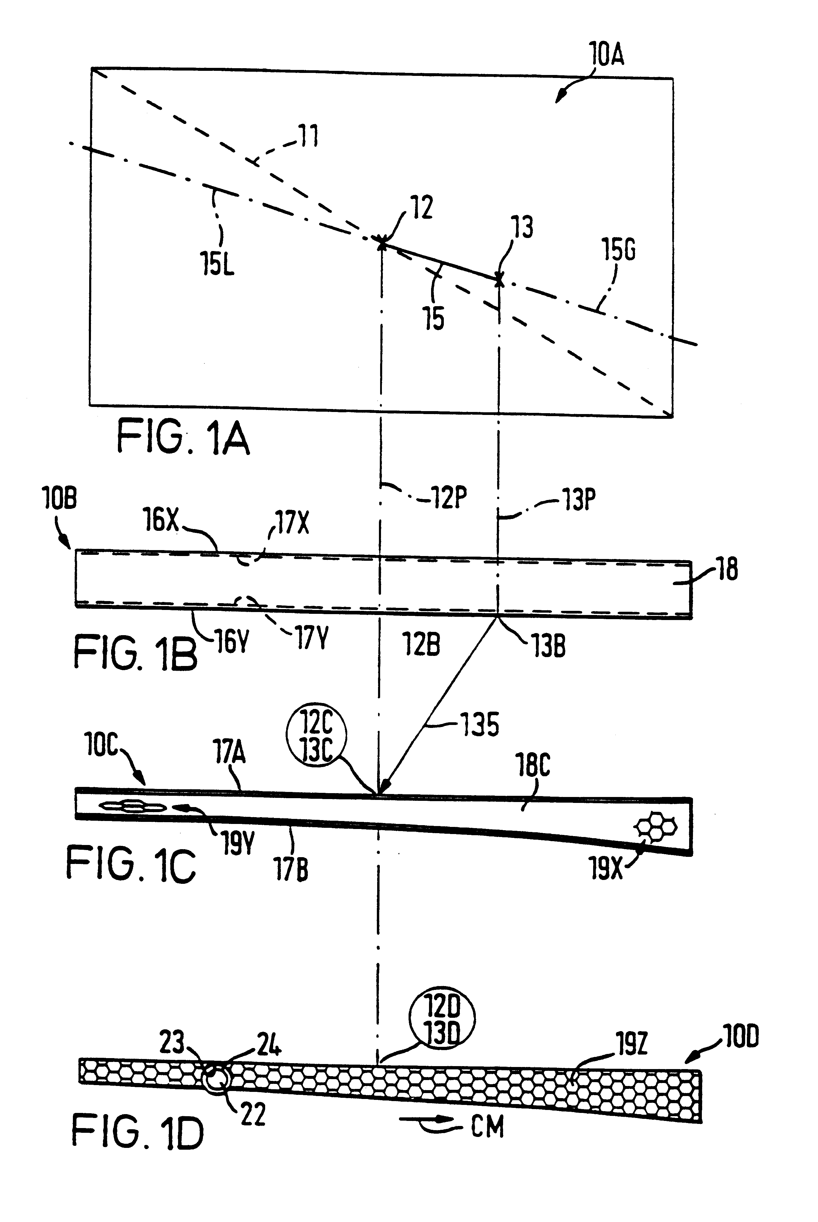
Referring first to FIG. 1A, a substantially rectangular acoustic distributed mode panel member 10A is indicated as though resulting directly from teachings of the two prior patent applications, thus having its "natural" location 13 for bending wave transducer means spaced from its geometrical centre 12 and off true diagonal shown dashed at 11. In application of the present invention, however, the transducer location 13 is to be at the geometric centre 12 of the panel member 10A, i.e. effectively to appear shifted along the solid line 15, which is achieved by appropriate areal distribution of bending stiffness of the panel member. To this end, the bending stiffness is made relatively greater and lesser to one side (right in FIG. 1A) and to the opposite side (left in FIG. 1C) of the geometric centre 12 and the "natural" transducer location 13, specifically in opposite directions along the line 15 and its straight-line extensions 15G and 15L, respectively.

FIG. 1B is an outline section ...


PUM


Abstract

Acoustic devices have members extending transversely of thickness and capable of sustaining bending waves causing consequential acoustic action by reason of areal distribution of resonant modes of natural bending wave vibration consonant with required achievable acoustic action of said member over a desired operative acoustic frequency range. Areal distribution of stiffness including variation(s) therein is used to get desired locations for bending wave transducers and / or good resonant mode acoustic action from inherently unfavorable shapes of members. Members with combined pistonic action drive and bending wave excitement at centers of mass and geometry are featured.

Description

This invention relates to acoustic devices capable of acoustic action by bending waves and typically (but not exclusively) for use in or as loudspeakers.BACKGROUND TO THE INVENTIONOur co-pending earlier patent application Ser. No. 08 / 707,012 includes general teaching as to nature, structure and configuration of acoustic panel members having capability to sustain and propagate input vibrational energy through bending waves in acoustically operative area(s) extending transversely of thickness usually (if not necessarily) to edges of the member(s). Specific teaching includes analyses of various specific panel configurations with or without directional anisotropy of bending stiffness through / across said area(s) so as to have resonant mode vibration components distributed over said area(s) beneficially for acoustic coupling with ambient air; and as to having determinable preferential location(s) within said area(s) for acoustic transducer means, particularly operationally active or movin...

Claims


Application Information

Patent Timeline
Patent Type & Authority Patents(United States)
IPC IPC(8): G07F9/02H04R5/02H04R7/00H04R1/22H04R1/24H04R7/04
CPCG07F9/02H04R1/24H04R7/045H04R5/02H04R2499/15H04R2440/07
Inventor AZIMA, HENRYCOLLOMS, MARTINHARRIS, NEIL
Owner NEW TRANSDUCERS LTD
Why Eureka
Try Eureka