Touch-sensitive interface comprising a force sensor

a force sensor and touch-sensitive technology, applied in the direction of user-computer interaction input/output, electric digital data processing, instruments, etc., can solve the problem of not allowing the force exerted by the finger to be quantified

Active Publication Date: 2020-12-08
HAP2U
View PDF19 Cites 3 Cited by
  • Summary
  • Abstract
  • Description
  • Claims
  • Application Information

AI Technical Summary

Problems solved by technology

However, although the performance of the capacitive detection is good for localizing an impact of a finger on a screen, it does not allow the force exerted by the finger to be quantified.

Method used


Image

  • Touch-sensitive interface comprising a force sensor
  • Touch-sensitive interface comprising a force sensor
  • Touch-sensitive interface comprising a force sensor

Examples


Embodiment Construction

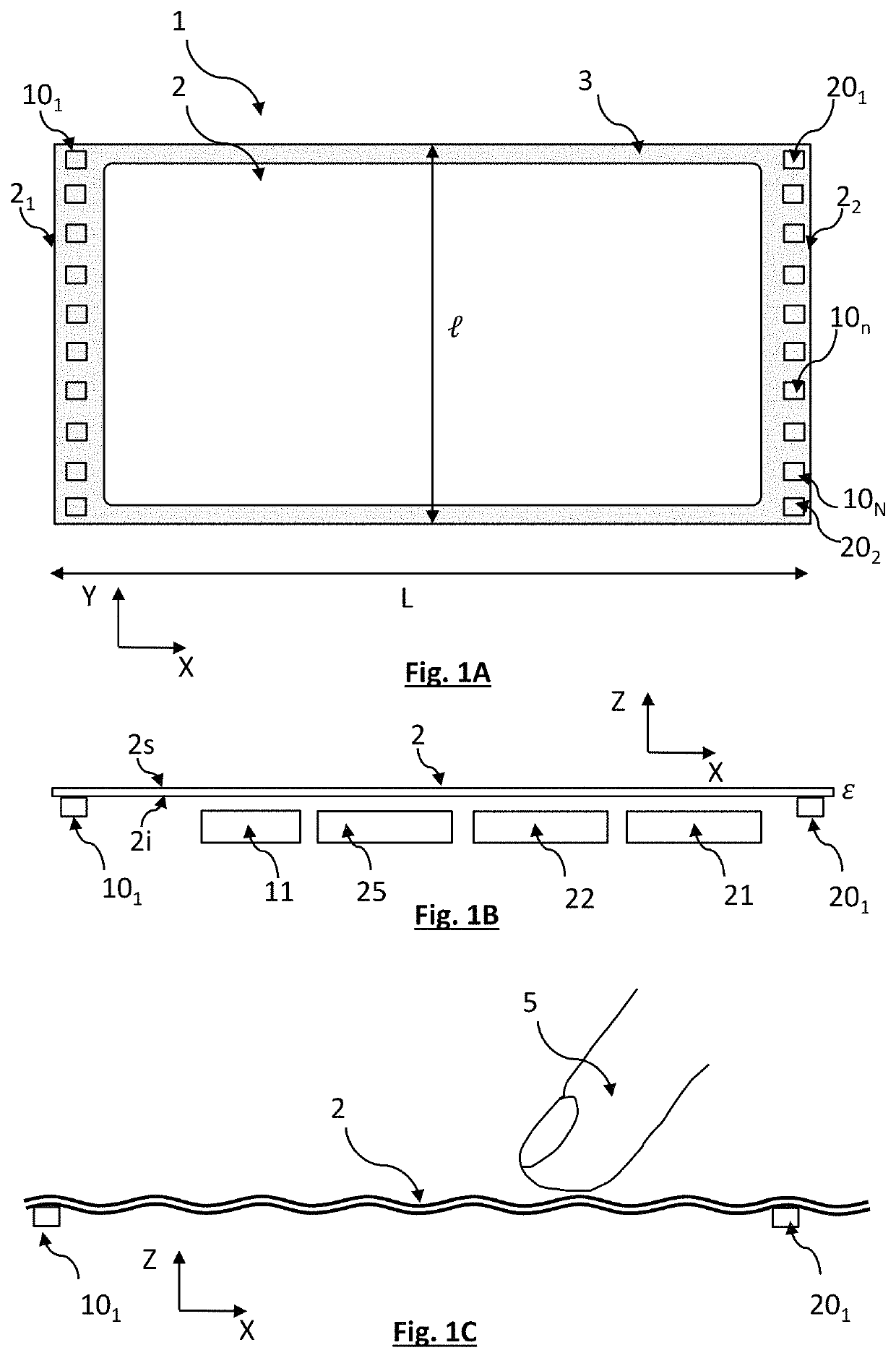
[0069]FIGS. 1A and 1B show one example of a touch-sensitive interface according to the disclosure. The interface comprises a plate 2, extending in a plane XY and forming, in this plane, a rectangle of length L (along the axis X) and of width l, (along the axis Y). In this example, L=195 mm, and l=125 mm. The thickness c of the plate, along the axis Z, is 1.5 mm. The term “plate” denotes a rigid element that is thin with respect to its width or its length. The width and the length are not critical parameters, and may be in the range between a few cm, for example, 3 cm, to 30 cm or more. The touch-sensitive interface 1 is designed to control a device, for example, a robotic machine or a microprocessor allowing the execution of a software program. Thus, the touch-sensitive interface is able to supply a control signal to the device.

[0070]The thickness c must allow a vibration of the plate 2 according to a stationary flexural wave 4, as described hereinafter. The thickness c depends on t...


PUM


Abstract

A touch-sensitive interface has a contact surface that is able to be touched by an effector (e.g., a finger). The interface includes actuating transducers (e.g., piezoelectric transducers) allowing a standing flexural wave to be formed, in a resonant mode, extending over the length of the slab. The interface includes a detector for measuring the amplitude of the wave, and a detecting circuit for determining an attenuation signal, when the contact surface is touched by an effector. It includes a processing circuit for estimating a magnitude of the force exerted by the effector on the contact surface.

Description

CROSS-REFERENCE TO RELATED APPLICATIONS[0001]This application is a national phase entry under 35 U.S.C. § 371 of International Patent Application PCT / FR2017 / 053866, filed Dec. 29, 2017, designating the United States of America and published in French as International Patent Publication WO 2018 / 127651 A1 on Jul. 12, 2018, which claims the benefit under Article 8 of the Patent Cooperation Treaty to French Patent Application Serial No. 1750047, filed Jan. 3, 2017.TECHNICAL FIELD[0002]Disclosed is a touch-sensitive interface, for example, a screen, designed to be touched by an effector, for example, a finger, the touch-sensitive interface being configured for measuring a force exerted by the effector touching the plate.BACKGROUND[0003]The increase in the use of touchscreens, notably applied to portable devices of the tablet or mobile telephone type, is being accompanied by numerous developments. These screens generally comprise a smooth contact surface on which it is possible to control...

Claims


Application Information

Patent Timeline
Patent Type & Authority Patents(United States)
IPC IPC(8): G06F3/041G06F3/044G06F3/01
CPCG06F3/016G06F3/044G06F2203/04105G06F3/041G06F3/03545G06F3/0416G06F3/0414
Inventor VEZZOLI, ERICCHAPPAZ, CÉDRICK
Owner HAP2U
Why Eureka
Try Eureka