
Connector for electrical fuse ignition device

a technology of fuse ignition and connection, which is applied in the direction of coupling device connection, pedestrian/occupant safety arrangement, vehicular safety arrangement, etc., can solve the problems of dangerous airbag accidental activation and absolute absence of operation

Inactive Publication Date: 2001-09-04
FRAMATOME CONNECTORS INT SA
View PDF6 Cites 40 Cited by
  • Summary
  • Abstract
  • Description
  • Claims
  • Application Information

AI Technical Summary

Benefits of technology

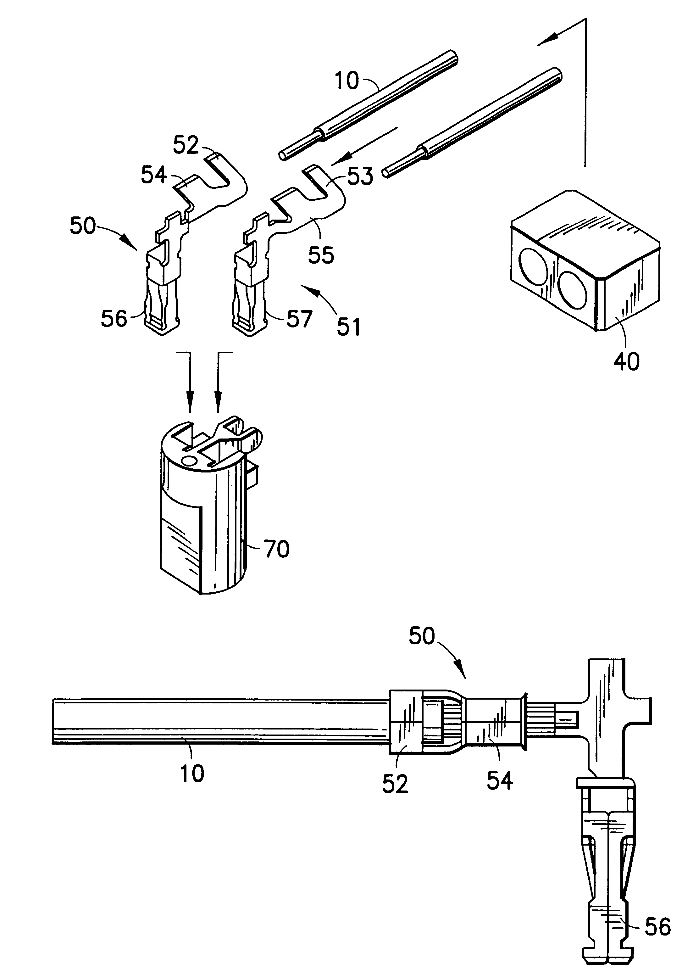
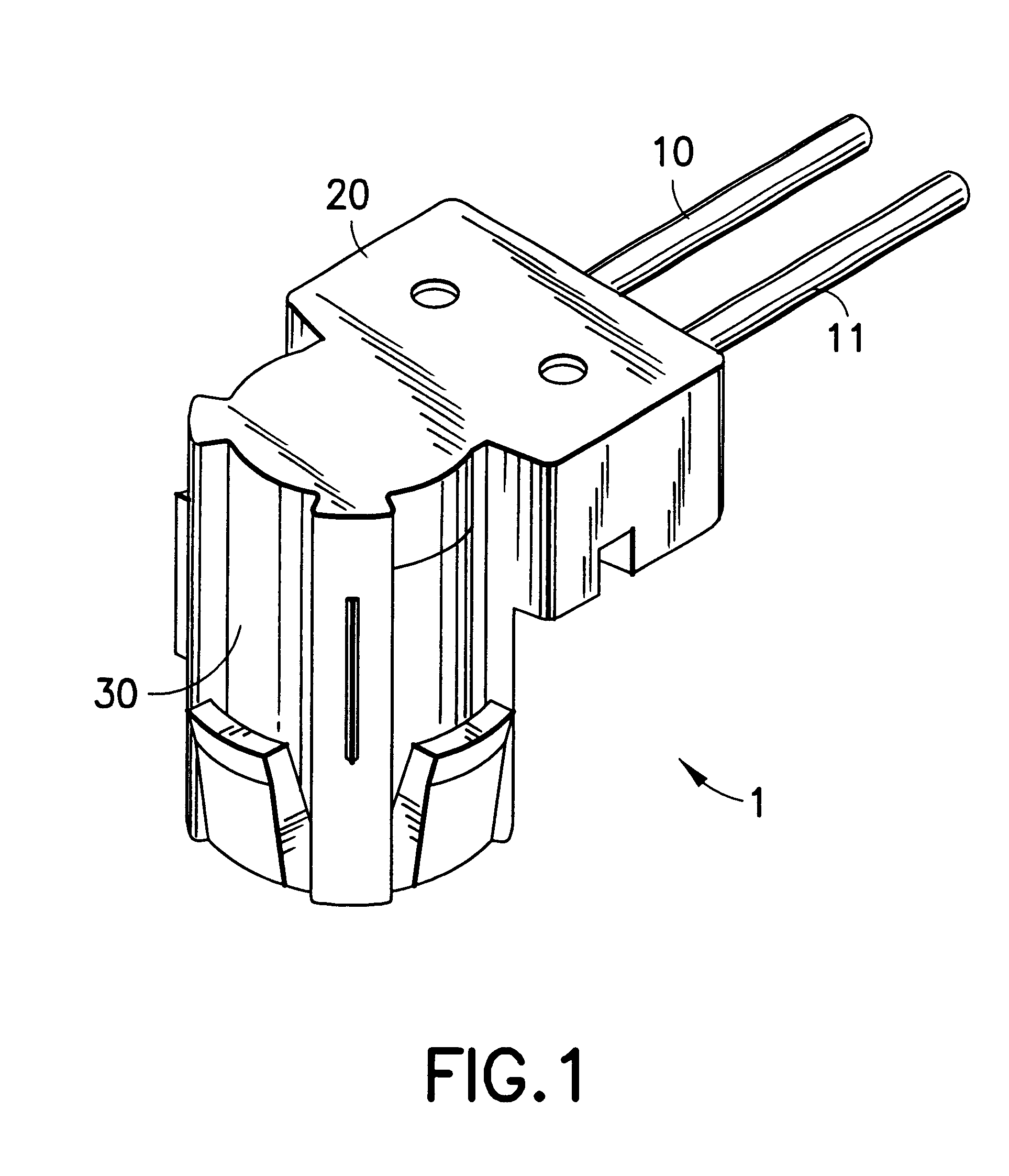
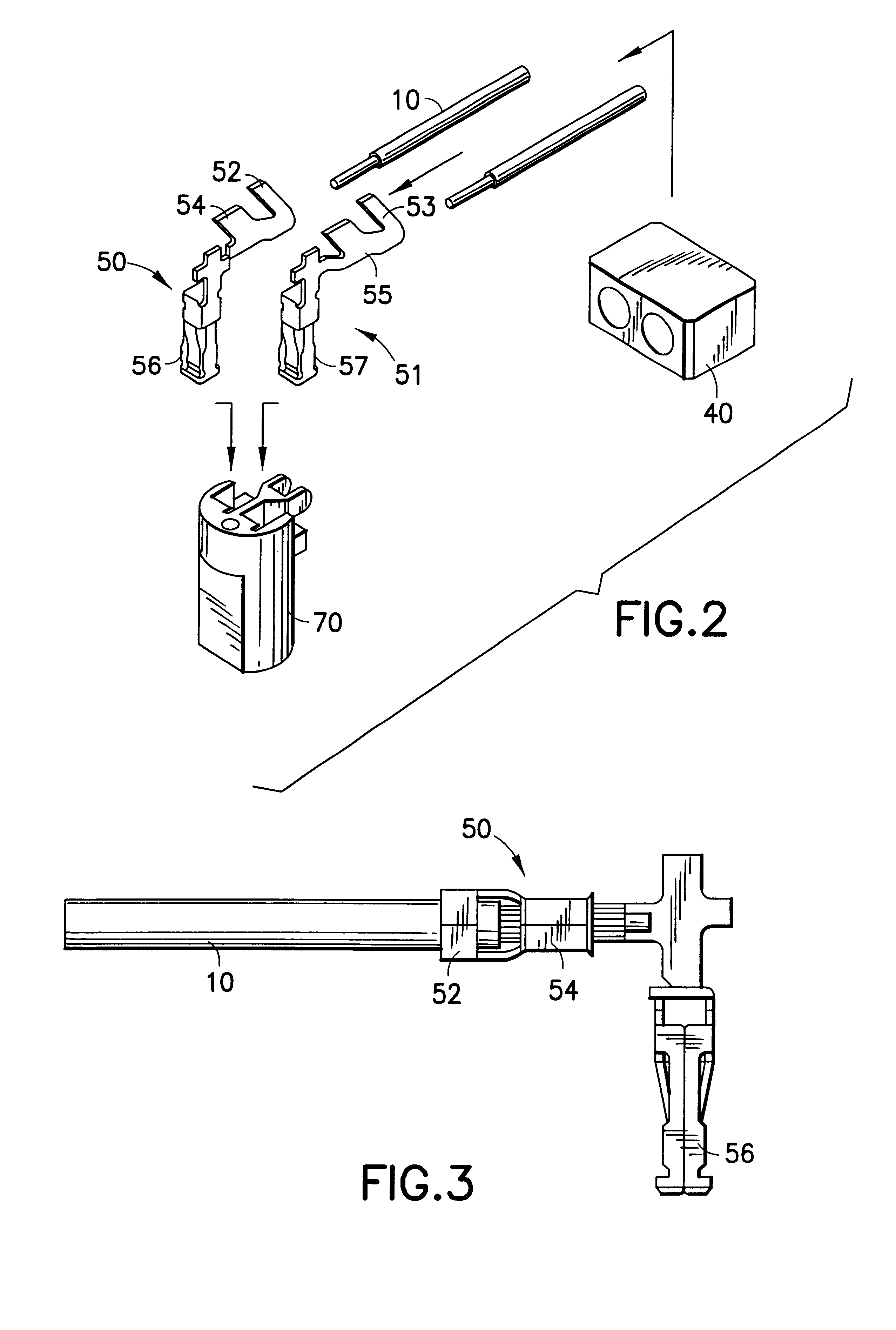
When the connector according to the present invention is used, if an attempt is made to mistakenly connect a lead which is different from a predetermined lead to the connector, the distance between the terminals and the distance between the terminal receiving holes will not match, thus making it impossible to make the connection. As a result, it is possible to completely eliminate errors in which the leads are mistakenly connected in an reversed manner. Furthermore, in the case of a connector provided with a projecting portion in the connector trunk portion, the projecting portion will interfere to obstruct insertion unless the relationship between the connector conductors and the axially-aligned holes into which they are to be inserted is correct, thereby even more completely eliminating connection errors.FIG. 1 is a perspective view showing a connector and portions of leads connecting to an electrical fuse ignition device according to the present invention.FIG. 2 is an exploded perspective view showing schematically the inside of a connector and leads.FIG. 3 is a side view showing the state of coupling of a connector conductor with a lead connected to an electrical fuse ignition device.FIG. 4 is a plan view showing the state of coupling of connector conductors with leads connected to an electrical fuse ignition device.FIG. 5 is a plan view showing a connector trunk portion.FIG. 6 is a plan view showing connector conductors in a state of insertion into a connector trunk portion along with leads connected to an electrical fuse ignition device gripped by the connector conductors.FIG. 7 is a plan view showing a ferrite member attached to the connector conductors and leads.FIG. 8 is a plan view showing a ferrite member.FIG. 9 is a side view showing a connector and a portion of a lead connected to an electrical fuse ignition device according to the present invention.FIG. 10 is a plan view showing a connector and portions of leads connected to an electrical fuse ignition device according to the present invention.

Problems solved by technology

While airbags must work reliably in the event of an emergency such as a collision, they ordinarily have absolutely no opportunity for operation from day to day.
Additionally, it is dangerous for the airbag to be activated accidentally when there is no emergency.

Method used


Image

  • Connector for electrical fuse ignition device
  • Connector for electrical fuse ignition device
  • Connector for electrical fuse ignition device

Examples


Embodiment Construction

Herebelow, embodiments of the present invention shall be described in detail with reference to the drawings.

FIG. 1 is a perspective view showing the outer appearance of a connector 1 according to the present invention. The connector 1 comprises a roughly cylindrical connector trunk portion housing portion 30 and a ferrite member housing portion 20 provided in the vicinity of one end of the connector trunk portion housing portion 30. The drawing shows how the ignition leads 10, 11 protrude from the ferrite member housing portion 20 roughly perpendicular to the axial direction of the connector trunk portion housing portion 30. While the ignition leads 10, 11 are partially omitted from the drawings, they extend further to eventually reach the electrical fuse ignition device. A pair of leads (not shown) are inserted from the bottom direction of the drawing into the connector 1 in the axial direction thereof, these leads being connected to the vehicle electrical system and supplying an i...


PUM


Abstract

The present invention has the aim of resolving the problem that there is a possibility of mistakes in wiring of connectors (1) not being discovered normally. A connector (1) for an electrical fuse ignition device comprising a pair of connector conductors (50, 51)adapted to grip a pair of leads (10, 11); a ferrite member (40) having a pair of through holes for accommodating the vicinities of one end of the pair of connector conductors (50, 51); and a connector trunk portion (70) having a pair of axially aligned holes (71, 72) for accommodating the vicinities of the other end of the connector conductors (50, 51), the connector (1) being characterized in that the shapes of said pair of connector conductors (50, 51) are non-identical such that the distance between the leads gripped when the other ends of said connector conductors (50, 51) are inserted into the axially-aligned holes (71, 72) of the connector trunk portion (70) is different from the distance between said axially-aligned holes (70, 71); and the distance between the pair of through holes provided in said ferrite member (40) is roughly equal to the distance between the leads (10, 11) when the connector conductors (50, 51) are inserted into the axially-aligned holes (71, 72) of said connector trunk portion (70).

Description

The present invention relates to an electrical connector for an electrical fuse ignition device which instantly activates a so-called airbag or the like. More specifically, the present invention relates to a connector for electrically connecting an electrical initiating device side with an electrical system side which supplies the initiating device with an electrical current.CONVENTIONAL ARTSo-called airbags are used as one type of passenger protection apparatus for vehicle collisions. An airbag, for example, can be a bag (airbag) composed of flexible materials accommodated in the vicinity of the central portion of a steering wheel, which instantly fills with gas in the event of a collision or the like so as to prevent the passengers from sustaining impacts or flying out.In order to instantly fill the airbag with gas, an explosive mixture is used, and an electrical fuse ignition device is used to ignite this mixture when required. Generally, the electrical system of the vehicle such...

Claims


Application Information

Patent Timeline
Patent Type & Authority Patents(United States)
IPC IPC(8): H01R4/10H01R4/18B60R21/16H01R13/642
CPCH01R4/186H01R4/184
Inventor OSUGA, TAKEHIKO
Owner FRAMATOME CONNECTORS INT SA
Learn More