Method and apparatus for dispensing viscous material

Inactive Publication Date: 2001-09-11
VISTEON GLOBAL TECH INC
View PDF15 Cites 27 Cited by
  • Summary
  • Abstract
  • Description
  • Claims
  • Application Information

AI Technical Summary

Problems solved by technology

Additionally, the nozzle tip member does not define a contained environment where "compression" of the filler material takes place through the mask followed by the immediate shearing off of the filler material within that contained environment from the surface of the stencil.
In fact, the nozzle tip member itself provides no effective means for shearing off filler material from the top of the stencil, rather, after the through hole is filled and filler material "backs up" through the stencil, the nozzle tip member moves forward whereupon the "excessive" filler material is then wiped off by a separate, single, flexible squeegee member which is designed for unidirectional use only.
Unfortunately, these conventional efforts do not provide a contained environment for compression of viscous material through holes in a stencil and shearing of viscous material within the contained environment from the upper surface of the stencil.
Reliance upon squeegee movement to force the viscous material, such as solder paste, through the stencil openings can lead to damage and eventual failure of both the squeegee blades and the stencil due to repeated friction.
Since conventional efforts do not provide a contained environment in which compression and shearing is accomplished, waste of the viscous material is frequently encountered.
Conventional efforts, therefore, (1) fail to maximize the efficiency of printing solder paste onto a desired area of a printed wiring board and (2) fail to minimize waste of the solder paste during the printing process.
Other prior viscous material dispensers utilizing compression print heads suffer from several drawbacks as

Method used


Image

  • Method and apparatus for dispensing viscous material
  • Method and apparatus for dispensing viscous material
  • Method and apparatus for dispensing viscous material

Examples


second embodiment

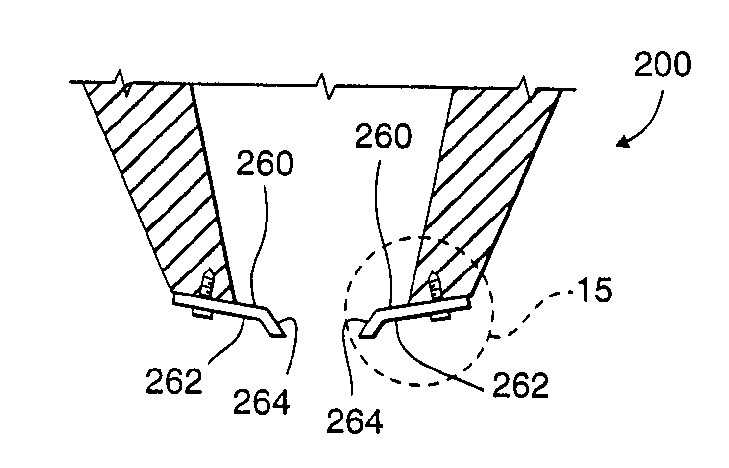
Referring now to FIGS. 6 through 11, there is shown a compression head 200 for use with the present invention. Particularly, head 200 is formed by the selective attachment of two substantially identical members 202 and 204 which are each preferably manufactured from a relatively strong, rigid, and durable material such as stainless steel or some other suitable conventional and commercially available metal or composite. Members 202 and 204 are also selectively coupled by the use of commercially available and conventional fasteners 206 and may be further joined by conventional welding or other attachment processes.

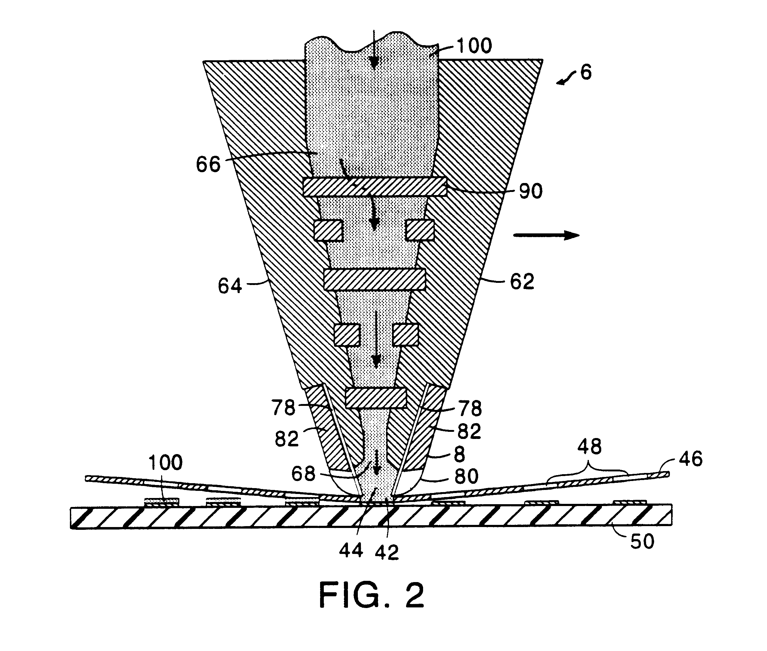
Members 202 and 204 cooperatively form at least one interior chamber 208 which, as shown best in FIG. 8, originates at a paste or viscous material reception input aperture 211 and gradually widens before terminating in a substantially rectangular elongated opening 212 which is generally and longitudinally coextensive to head 200 and which is substantially similar to the prev...

third embodiment

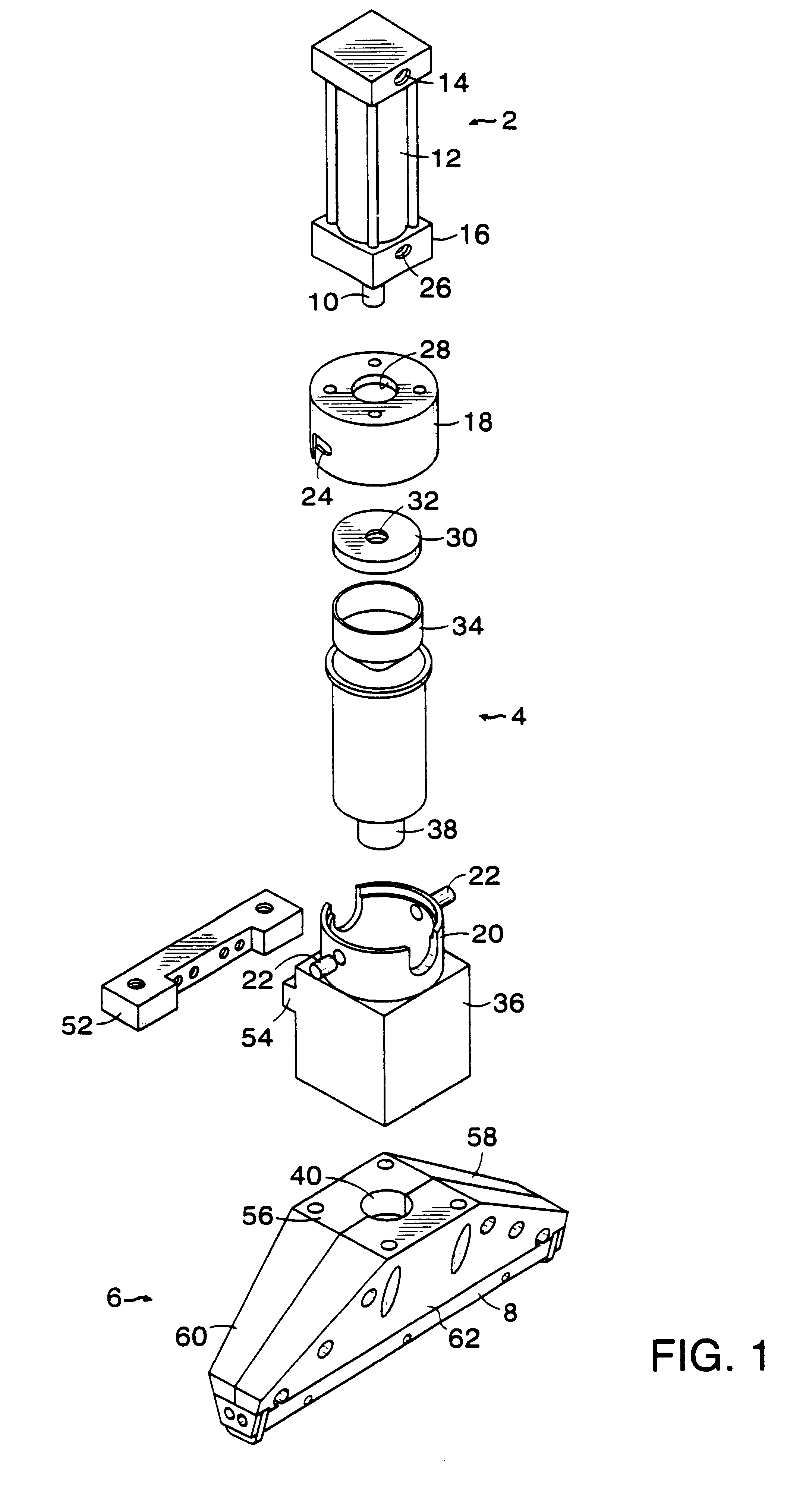
Referring now to FIGS. 19 and 20, there is shown an apparatus 300 which selectively dispenses viscous material and which is made in accordance with the teachings of the invention.

Particularly, apparatus 300 includes a compression head 301 which includes substantially identical components as head 200. Unless otherwise specified below, components having a substantially identical structure and function are defined by the same reference numerals as those components of head 200 which was previously delineated in FIGS. 6 through 8, with the exception that these components will have reference numerals which are incremented by 100.

Apparatus 300 further includes a generally cylindrical paste or viscous material dispenser 317 having a vertically extending support member 319 which is selectively and movably connected to a support beam 323 by use of a conventional and commercially available attachment member 321. Particularly, member 321 moveably engages support beam 323 in a conventional manne...


PUM


Abstract

A novel apparatus for compressing viscous material through openings in a stencil is disclosed. The novel apparatus has a compression head cap which provides a contained environment to direct and to aid the flow of pressurized viscous material through the openings in the stencil.

Description

1. Field of the InventionEmbodiments of the present invention relate generally to methods and devices for depositing viscous materials onto a printed wiring board. In one aspect, the present invention relates to methods and devices for compressing viscous materials, such as solder paste, through openings in a perforated substrate, such as a patterned screen or stencil.2. Description of Related ArtSurface Mount Technology (SMT) involves placing circuit components onto circuit paths embedded on the upper surface of a printed wiring board and then soldering the components in place by a process called "reflow soldering". Before the circuit component is placed on the printed wiring board, however, it is desirable to apply solder paste to the area on the printed wiring board where the component is to be soldered into place.Conventional methods do exist to deposit ("print") solder paste onto desired areas of a printed wiring board by forcing the paste through openings in a substrate (e.g.,...

Claims


Application Information

Patent Timeline
IPC IPC(8): B41F15/40B41F15/42H05K3/12B05C5/00B05C11/04B41F15/08B41F15/44H05K3/34
CPCB41F15/42H05K3/1233B41F15/44H05K2203/0126
Inventor LIN, JEFFTRUBLOWSKI, JOHNHA, VINH VAN
Owner VISTEON GLOBAL TECH INC
Why Eureka
Try Eureka