Threaded spinal implant with bone ingrowth openings

a technology of ingrowth openings and spinal implants, applied in the field of surgical procedures for stabilizing the spine, can solve the problems of most common and perplexing, chronic low back pain, severe adverse societal effects, and low back pain

Inactive Publication Date: 2001-09-11
ZIMMER SPINE INC
View PDF75 Cites 153 Cited by
  • Summary
  • Abstract
  • Description
  • Claims
  • Application Information

AI Technical Summary

Problems solved by technology

Chronic low back pain is one of the most common and perplexing problems facing the field of orthopedic surgery.
In addition to patient discomfort, chronic low back pain has severe adverse societal impacts including lost income, possible chronic dependence on drugs, alcohol and public relief programs.

Method used


Image

  • Threaded spinal implant with bone ingrowth openings
  • Threaded spinal implant with bone ingrowth openings
  • Threaded spinal implant with bone ingrowth openings

Examples


Embodiment Construction

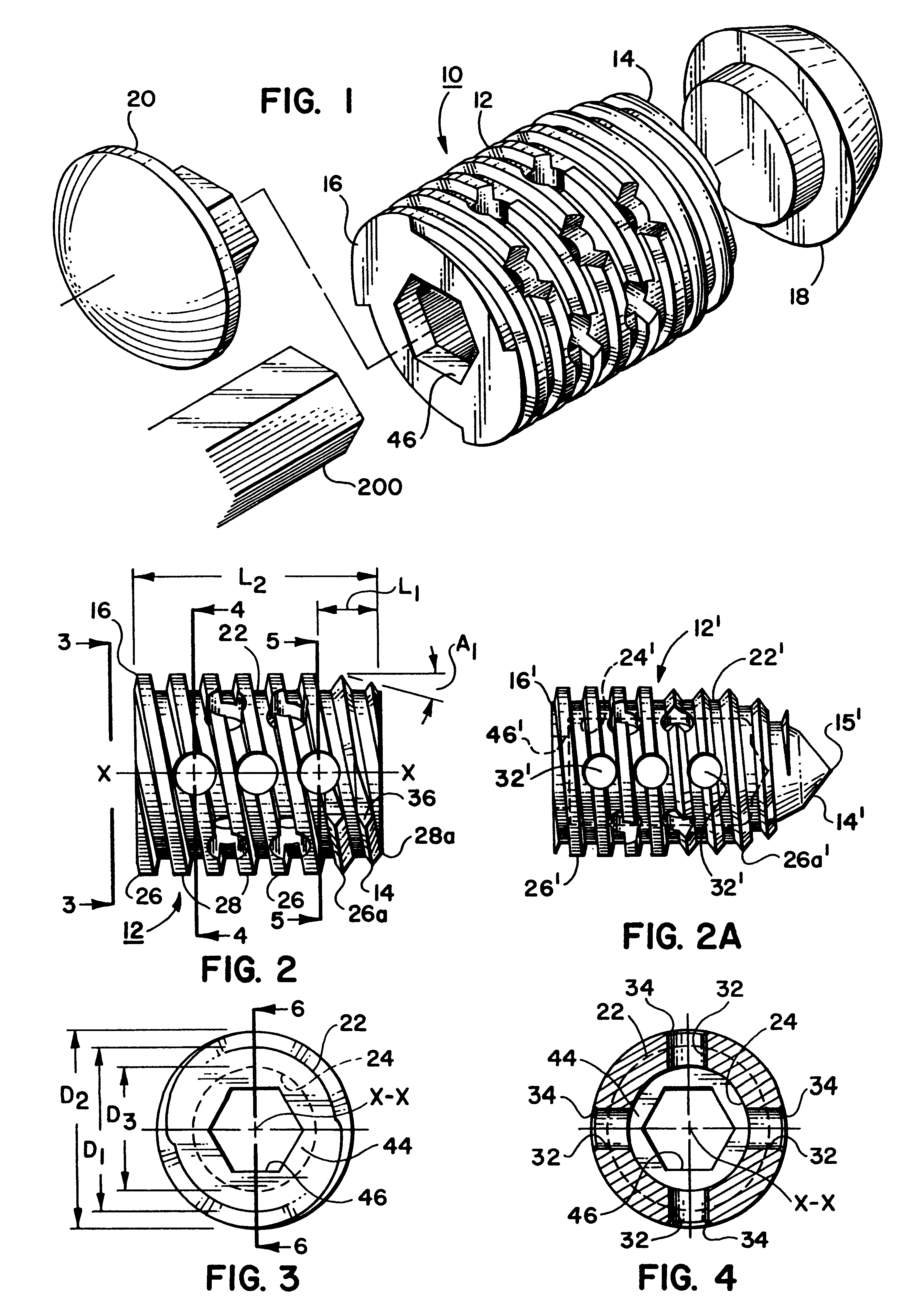
With reference now directed to FIGS. 1-12, a first preferred embodiment of the present invention will now be described. Identical elements are numbered identically throughout.

The implant 10 includes a body 12 (shown separately in FIGS. 2, 3-6) having a leading end 14 and a trailing end 16 which are spaced apart along a longitudinal axis X--X of the body 12. The implant also includes a leading end cap 18 and a trailing end cap 20 (shown separately in FIGS. 8-9 and FIGS. 10-11, respectively).

Body 12 is integrally constructed from a rigid, biocompatible material. While any rigid, biocompatible material (such as a ceramic) could be used, body 12 is preferably formed from titanium and / or its alloys. Titanium and / or its alloys is preferred since it is noncorrosive and fatigue resistent. Also, titanium is widely used in prosthetic devices and the material has a proven record of satisfactory performance.

With best reference to FIGS. 2-7 and 7A, the body 12 includes a hollow cylindrical shell...


PUM


Abstract

An implant is disclosed for use in spinal stabilization. In one preferred embodiment, the implant is described as including a hollow, cylindrical body having external threading and a plurality of openings formed radially through the body in communication with the body interior. The holes are positioned to chip bone into the implant as the implant is rotated.

Description

1. Field of the InventionThis invention pertains to surgical procedures for stabilizing the spine. More particularly, this invention pertains to a novel implant for use in such a procedure.2. Description of the Prior ArtChronic low back pain is one of the most common and perplexing problems facing the field of orthopedic surgery. In addition to patient discomfort, chronic low back pain has severe adverse societal impacts including lost income, possible chronic dependence on drugs, alcohol and public relief programs.In many cases, low back pain can be avoided by preventing relative motion between spinal vertebrae (commonly referred to as intervertebral stabilization). To abate low back pain, stabilization is directed to stabilizing contiguous vertebrae in the lumbar region of the spine.Surgical techniques are known for use in spinal stabilization. Surgical techniques seek to rigidly join vertebrae which are separated by a degenerated disk. Ideally, the surgery effectively replaces th...

Claims


Application Information

Patent Timeline
Patent Type & Authority Patents(United States)
IPC IPC(8): A61F2/30A61F2/44A61B17/88A61F2/28A61F2/00A61F2/46
CPCA61F2/4455A61F2/446A61F2/30744A61B17/8875A61F2310/00179A61F2/442A61F2/4611A61F2002/2835A61F2002/30125A61F2002/30143A61F2002/30217A61F2002/30235A61F2002/305A61F2002/30617A61F2002/30772A61F2002/30777A61F2002/30785A61F2002/30787A61F2002/30789A61F2002/30846A61F2002/3085A61F2002/30851A61F2002/30853A61F2002/30868A61F2002/4475A61F2220/0025A61F2230/0008A61F2230/0017A61F2230/0067A61F2230/0069A61F2250/0097A61F2310/00023Y10S606/907A61F2002/30845A61F2002/30593
Inventor KUSLICH, STEPHEN D.CORIN, JAMES DONALDBAGBY, GEORGE W.
Owner ZIMMER SPINE INC
Why Eureka
Try Eureka