Open transmission line intrusion detection system using frequency spectrum analysis

a technology of intrusion detection and frequency spectrum analysis, applied in the field of open transmission line intrusion detection system using frequency spectrum analysis, can solve the problems of increased likelihood of undetected intrusion, increased cost, and difficulty in setting sensitivity, and achieve the effect of being affordable yet reliabl

Inactive Publication Date: 2001-09-11
AURATEK SECURITY
View PDF8 Cites 95 Cited by
  • Summary
  • Abstract
  • Description
  • Claims
  • Application Information

AI Technical Summary

Benefits of technology

The present invention seeks to eliminate, or at least mitigate, one or more of the disadvantages of known intrusion detection systems and to provide an intrusion detection system which is relatively inexpensive yet reliable.

Problems solved by technology

Such duplication entails additional expense.
A disadvantage of this approach, however, is that long sensor lines can increase the likelihood of undetected intrusion.
Thus, attenuation along the length of the line may make it difficult to set the sensitivity so that the system will detect an intruder at the far end of the line while not being overloaded by perturbations caused by an intruder near to the receiver.
Graded cables could be used to overcome this problem, but they are relatively expensive.
Another disadvantage of long sensor lines concerns the need to allow legitimate access to a protected area such as a compound.
When a sensor line across the entrance to a compound is switched off to allow a vehicle to enter, for example, the risk of an intruder gaining access at the same time is greater for longer sensor lines.
Other problems which are exacerbated by longer sensor lines include variations in sensitivity caused by differing media along the length of the line; objects moving within the protected area; and increased range capability for any video monitors used in conjunction with the system.

Method used


Image

  • Open transmission line intrusion detection system using frequency spectrum analysis
  • Open transmission line intrusion detection system using frequency spectrum analysis
  • Open transmission line intrusion detection system using frequency spectrum analysis

Examples


Embodiment Construction

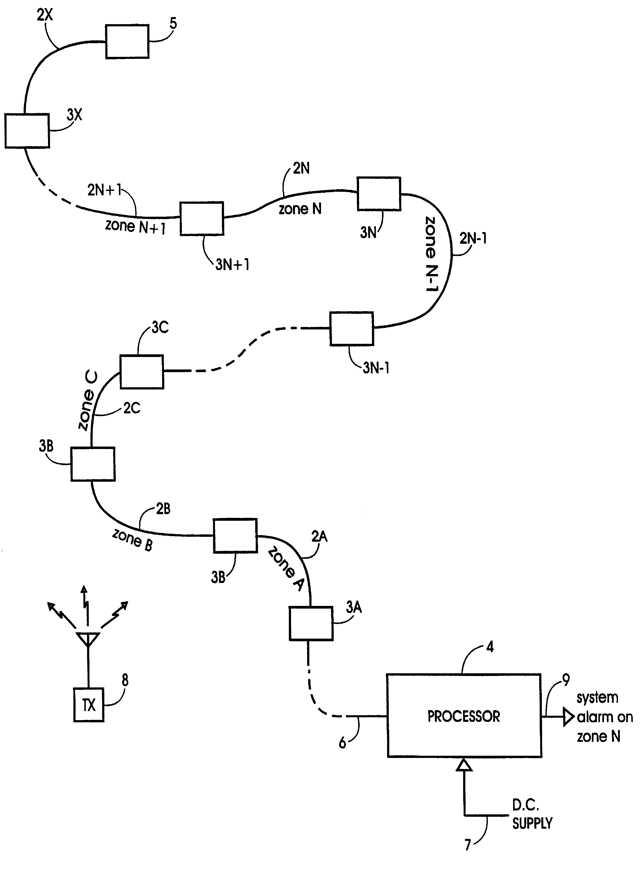
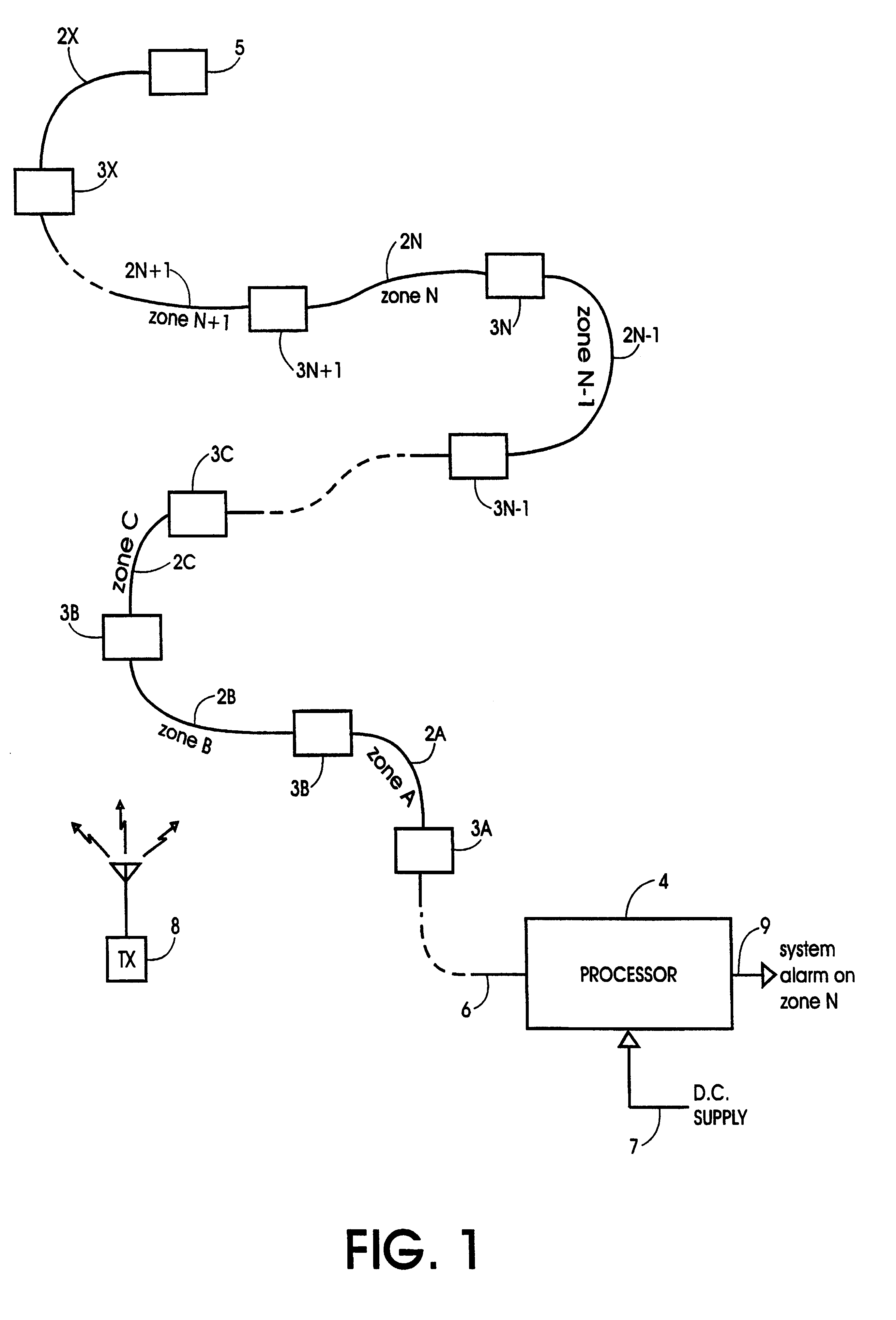
Referring first to FIG. 1, an intrusion detection system comprises a series of similar open transmission lines in the form of so-called "leaky" or "ported" cables designated 2A, 2B, 2C . . . 2N . . . 2X and receivers, designated 3A, 3B, 3C . . . 3N . . . 3X, connected in series between a common processor 4 and a termination load 5 to form, in effect, a linear bus defining a corresponding series of protection zones A to X. The cables 2A . . . 2X serve as sensors. The common processor 4 is connected to the first receiver 3A by a feedline 6 and connected to a DC power supply by line 7. The common processor 4 relays DC power to the receivers 3 by way of the feedline 6 and cable or cables 2. The final cable 2X is connected at one end to the termination load 5 and at the other end to receiver 3X. A separate transmitter 8 broadcasts FM radio signals which are received by the cables 2A . . . 2X. Preferably, the transmitter 8 is a commercial FM radio station transmitter broadcasting a multip...


PUM


Abstract

An intrusion detection system comprises a plurality of sensors (2A . . . 2X) and a corresponding plurality of receivers (3A. . . 3X). Each receiver receives, via the associated sensor, radio frequency signals comprising a multiplicity of transmissions at different frequencies within a predetermined frequency spectrum. The receiver detects the radio frequency signals and computes, for each of a plurality of successive time intervals and for each of the transmission frequencies, a measurement of signal amplitude over the time interval; compares such signal amplitude measurement with at least one threshold and, if the amplitude exceeds the threshold for a predetermined time period, generates a potential alarm signal. A processor (4) compares potential alarm signals from a plurality of sensors and determines that an intrusion has occurred if the potential alarm signal for a particular station does not coincide with a potential alarm signal for a neighboring sensor. Each receiver may output an intruder alarm signal when potential alarm signals occur simultaneously for more than a preset number of a multiplicity of the transmission frequencies.

Description

DESCRIPTION1. Technical FieldThe invention relates to intrusion detection systems and is especially applicable to systems which comprise an "open" transmission line, for example a so-called "leaky" or "ported" cable, for receiving a radio frequency signal and a receiver attached to the open transmission line for processing the received radio frequency signal to detect perturbations caused by an intruder in proximity to the open transmission line.2. Background ArtExamples of such intrusion detection systems are disclosed in U.S. Pat. No. 3,163,861 (Suter) issued Dec. 29, 1964, U.S. Pat. No. 3,794,992 (Gehman) issued Feb. 26, 1974, U.S. Pat. No. 4,419,659 (Harman et al) issued Dec. 6, 1983, U.S. Pat. No. 4,887,069 (Maki) issued Dec. 12, 1989 and international patent application number PCT / CA93 / 00366 (Harman et al) published Mar. 31, 1994.To increase detection rates, the system disclosed by Gehman compares the signals from two adjacent cables, one via a quarter-wavelength section. Such...

Claims


Application Information

Patent Timeline
Patent Type & Authority Patents(United States)
IPC IPC(8): G08B13/24
CPCG08B13/2497
Inventor GAGNON, ANDRE
Owner AURATEK SECURITY
Why Eureka
Try Eureka