Heat pump with an auxiliary heat exchanger for compressor discharge temperature control

a heat pump and compressor technology, applied in the field of airconditioning equipment, can solve the problems of insufficient cooling capacity or heating capacity, insufficient cooling capacity, damage to the compressor, etc., and achieve the effect of limiting the rise in the temperature of refrigerant discharged and improving the reliability of the system inexpensively

Active Publication Date: 2019-02-19
MITSUBISHI ELECTRIC CORP
View PDF33 Cites 0 Cited by
  • Summary
  • Abstract
  • Description
  • Claims
  • Application Information

AI Technical Summary

Benefits of technology

[0010]With the air-conditioning apparatus according to the present invention, the state and flow rate of refrigerant routed into the suction part of the compressor from the bypass pipe are controlled by using the auxiliary heat exchanger, the flow regulating unit, and the second expansion device under all operating conditions to limit a rise in the temperature of refrigerant discharged from the compressor. This configuration allows the reliability of the system to be improved inexpensively without employing a special structure for the compressor.

Problems solved by technology

The high discharge temperature causes problems such as degradation of the refrigerating machine oil, leading to damage to the compressor.
This makes it impossible to increase the rotation speed of the compressor, leading to insufficient cooling capacity or insufficient heating capacity.

Method used


Image

  • Heat pump with an auxiliary heat exchanger for compressor discharge temperature control
  • Heat pump with an auxiliary heat exchanger for compressor discharge temperature control
  • Heat pump with an auxiliary heat exchanger for compressor discharge temperature control

Examples


embodiment 1

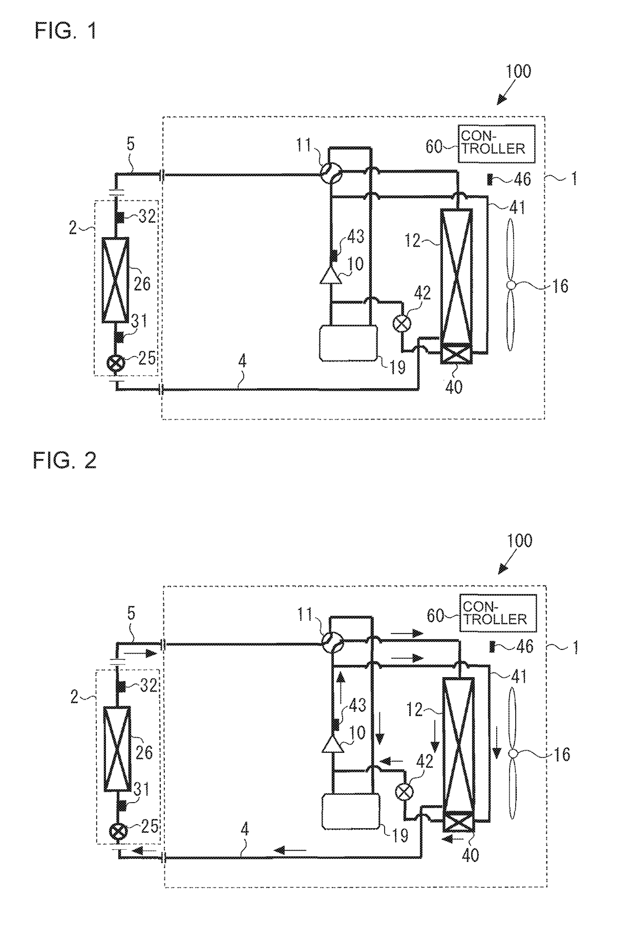
[0024]Hereinafter, an air-conditioning apparatus according to Embodiment 1 of the present invention will be described with reference to the drawings. FIG. 1 is a schematic circuit configuration diagram illustrating an exemplary circuit configuration of the air-conditioning apparatus according to Embodiment 1. An air-conditioning apparatus 100 illustrated in FIG. 1 includes an outdoor unit 1 and an indoor unit 2 that are connected by a main pipe 5. Although a single indoor unit 2 is connected to the outdoor unit 1 via the main pipe 5 in FIG. 1, this is not intended to limit the number of indoor units 2 to one. Alternatively, a plurality of indoor units 2 may be connected.

[Outdoor Unit 1]

[0025]In the outdoor unit 1, a compressor 10, a refrigerant flow switching device 11, a heat source-side heat exchanger 12, an accumulator 19, an auxiliary heat exchanger 40, a flow regulating unit 42, and a bypass pipe 41 are connected by a refrigerant pipe 4 (refrigerant pipes 4), and are mounted to...

embodiment 2

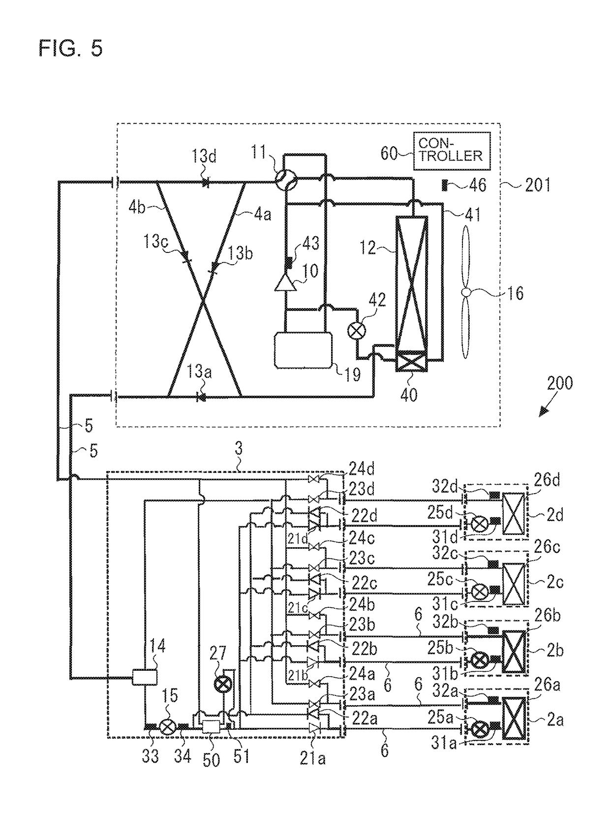
[0083]FIG. 5 is a refrigerant circuit diagram illustrating an exemplary circuit configuration of an air-conditioning apparatus according to Embodiment 2 of the present invention. An air-conditioning apparatus 200 will be described below with reference to FIG. 5. In FIG. 5, parts configured in the same manner as those in the air-conditioning apparatus 100 illustrated in FIG. 1 will be denoted by the same reference signs to omit a description of these parts.

[0084]The air-conditioning apparatus 200 illustrated in FIG. 5 has a single outdoor unit 201, which is a heat source unit, a plurality of indoor units 2a to 2d, and a relay device 3 with an opening and closing device provided between the outdoor unit 201 and each of the indoor units 2a to 2d. The outdoor unit 201 and the relay device 3 are connected by the main pipe 5 through which refrigerant flows, and the relay device 3 and the indoor units 2a to 2d are connected by a branch pipe 6 through which refrigerant flows. The cooling en...

embodiment 3

[0134]FIG. 10 is a refrigerant circuit diagram illustrating the flow of refrigerant in heating only operation mode of an air-conditioning apparatus according to Embodiment 3. The following description of Embodiment 3 will mainly focus on differences from Embodiment 2, and parts that are the same as those in Embodiment 2 will be denoted by the same reference signs. An air-conditioning apparatus 300 illustrated in FIG. 10 differs from the air-conditioning apparatus 200 illustrated in FIGS. 5 to 9 in the configuration of an outdoor unit 301.

[0135]In the outdoor unit 301 of the air-conditioning apparatus 300, one end of the bypass pipe 41 is connected to the part of the refrigerant pipe 4 between the first backflow prevention device 13a and the main pipe 5.

[0136]When a rise in the temperature of refrigerant discharged from the compressor 10 is to be limited in cooling only operation mode and cooling main operation mode, a part of the high-pressure liquid refrigerant exiting the heat sou...


PUM


Abstract

An air-conditioning apparatus includes a bypass pipe that has one end connected to the discharge side of a compressor and through which refrigerant exiting the compressor flows, an auxiliary heat exchanger that is connected to the other end of the bypass pipe and the suction part of the compressor, and cools refrigerant flowing through the bypass pipe and supplies the cooled refrigerant to the suction part of the compressor, and a flow regulating unit that is provided on the refrigerant outlet side of the auxiliary heat exchanger, and regulates the flow rate of refrigerant routed into the suction part of the compressor from the auxiliary heat exchanger.

Description

TECHNICAL FIELD[0001]The present invention relates to an air-conditioning apparatus used as, for example, a multi-air-conditioning unit for buildings.BACKGROUND ART[0002]Some of air-conditioning apparatuses known in related art, such as multi-air-conditioning units for buildings, have a refrigerant circuit in which, for example, an outdoor unit to serve as a heat source unit disposed outside a building, and an indoor unit disposed inside the building are connected by pipes. Refrigerant circulates in the refrigerant circuit, and air is heated or cooled by utilizing the rejection or absorption of heat by the refrigerant, thus heating or cooling the air-conditioning target space. In recent years, air-conditioning apparatuses employing fluorocarbon refrigerants with low global warming potentials, such as an R32 refrigerant, have been considered for use in multi-air-conditioning units for buildings.[0003]As opposed to an R410A refrigerant widely used in conventional air-conditioning appa...

Claims


Application Information

Patent Timeline
Patent Type & Authority Patents(United States)
IPC IPC(8): F25B13/00F25B31/00F25B41/04F25B49/02
CPCF25B13/00F25B41/04F25B41/043F25B49/02F25B31/006F25B2700/21152F25B2313/006F25B2313/021F25B2313/0231F25B2313/0233F25B2313/0272F25B2313/02732F25B2313/02741F25B2313/0311F25B2313/0314F25B2400/05F25B2400/13F25B2400/23F25B2500/08F25B2600/0261F25B2600/0271F25B2600/2501F25B2700/2106F25B41/20F25B41/24
Inventor IKEDA, SOSHIWAKAMOTO, SHINICHITAKENAKA, NAOFUMIYAMASHITA, KOJIHATOMURA, TAKESHI
Owner MITSUBISHI ELECTRIC CORP
Why Eureka
Try Eureka