Controller and management system for injection molding machine

a management system and injection molding machine technology, applied in the field of controller and management system of injection molding machine, can solve problems such as machine failure, and achieve the effects of suppressing machine breakage and other failures due to excessive clamping force, limiting the rise of driving current, and preventing excessive clamping for

Active Publication Date: 2019-05-21
FANUC LTD
View PDF17 Cites 0 Cited by
  • Summary
  • Abstract
  • Description
  • Claims
  • Application Information

AI Technical Summary

Benefits of technology

[0006]The present invention has been devised in view of the above circumstances, it is therefore an object of the present invention to provide a controller and a management system for an injection molding machine, which can avoid application of excessive clamping force by a simple structure and accurately determine abnormality of a clamping force sensor.
[0009]According to the present invention, the controller and management system of the injection molding machine sets an upper limit of driving current during clamping to limit the rise of the driving current by the motor drive control unit, whereby it is possible to prevent the clamping force from being applied excessively to the movable and fixed molds. That is, breakage of the machine and other failures due to excessive clamping force can be suppressed with a simple structure. Further, it is determined that a large clamping force is applied to the movable and fixed molds if the driving current is limited. In addition, the controller or the central management device detects stoppage of movement of the movable mold during mold clamping, so that it is possible to accurately determine occurrence of an abnormality of the clamping force detector. Thus, it is possible to detect an abnormality of the clamping force detector at an early stage and suppress manufacturing defects of molded products, damage to the machine, and other faults.

Problems solved by technology

However, when an abnormality occurs in the clamping force sensor, the adjustment of the clamping force itself results in failure.
If such adjustment failure occurs, there is a risk that, for example, the injection molding machine generates an excessive clamping force between the fixed and movable molds in mold-clamping, thereby causing machine failure or some other problems.

Method used


Image

  • Controller and management system for injection molding machine
  • Controller and management system for injection molding machine
  • Controller and management system for injection molding machine

Examples


first embodiment

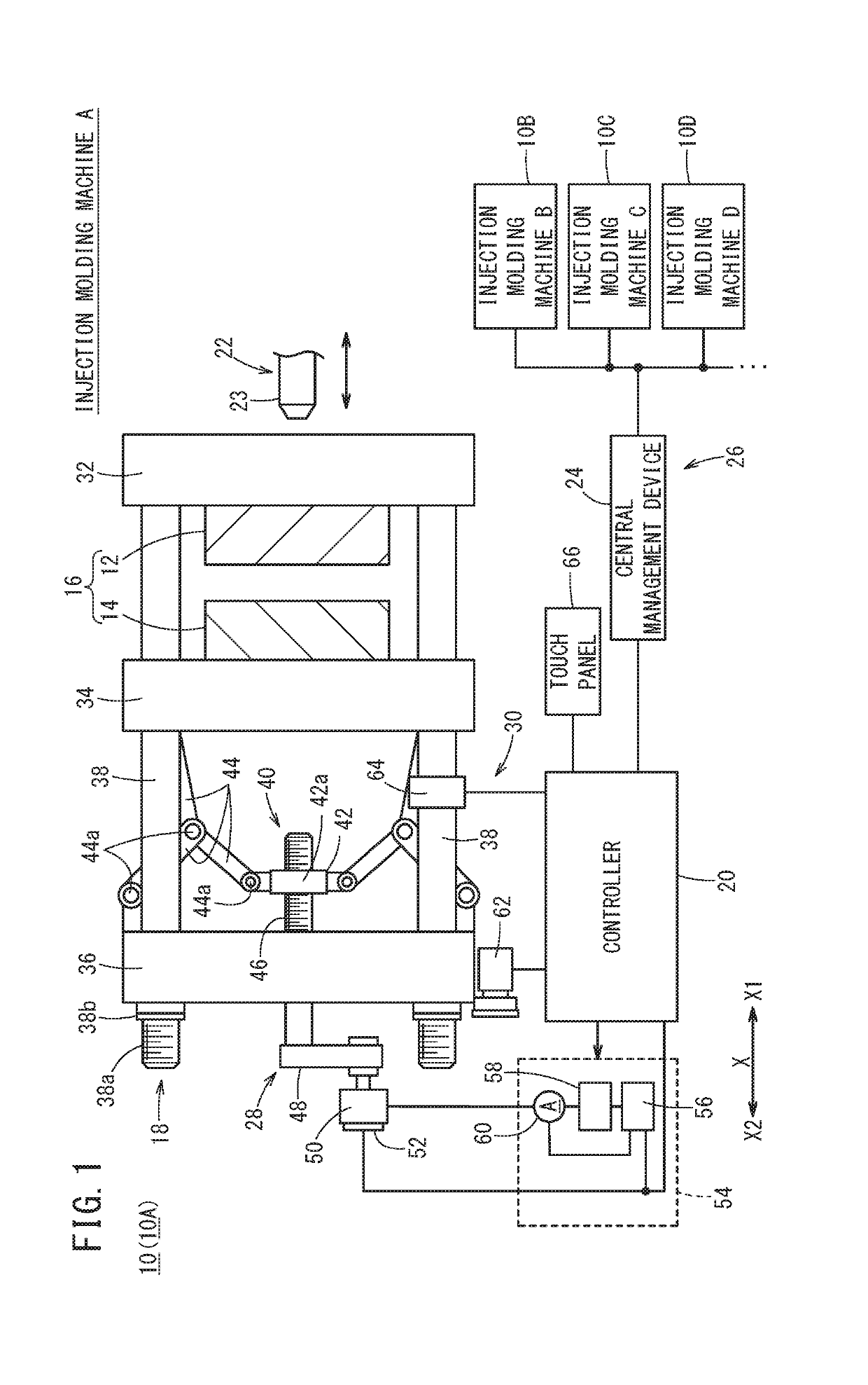
[0022]As shown in FIG. 1, an injection molding machine 10 according to the first embodiment of the present invention forms a molded product (not shown) by clamping an injection mold 16 (die) made up of a fixed mold 12 and a movable mold 14 and injecting a molding material into a cavity formed in the injection mold 16. The injection molding machine 10 includes a mold clamping device 18 for clamping the mold 16, a mold clamping controller 20 for controlling the mold clamping device 18, an injection device 22 for injecting a resin material into the clamped injection mold 16, and an injection controller (not shown) for controlling the injection device 22. It is noted that the mold clamping controller 20 may be configured to control the injection device 22 together with the mold clamping device (that is, control the entire operation of the injection molding machine 10). Hereinafter, the mold clamping controller 20 will be simply referred to as the controller 20.

[0023]Further, in factorie...

second embodiment

[0090]A controller 20A of the injection molding machine 10 according to a second embodiment of the present invention differs from the controller 20 according to the first embodiment in that while controlling the driving of the mold clamping servomotor 50 without setting any upper limit U1 on the driving current, the controller 20A determines abnormality of the clamping force sensor 64 by monitoring the driving current detected by the ammeter 60. In the following description, the same components as those in the first embodiment are denoted by the same reference numerals, and description thereof is omitted.

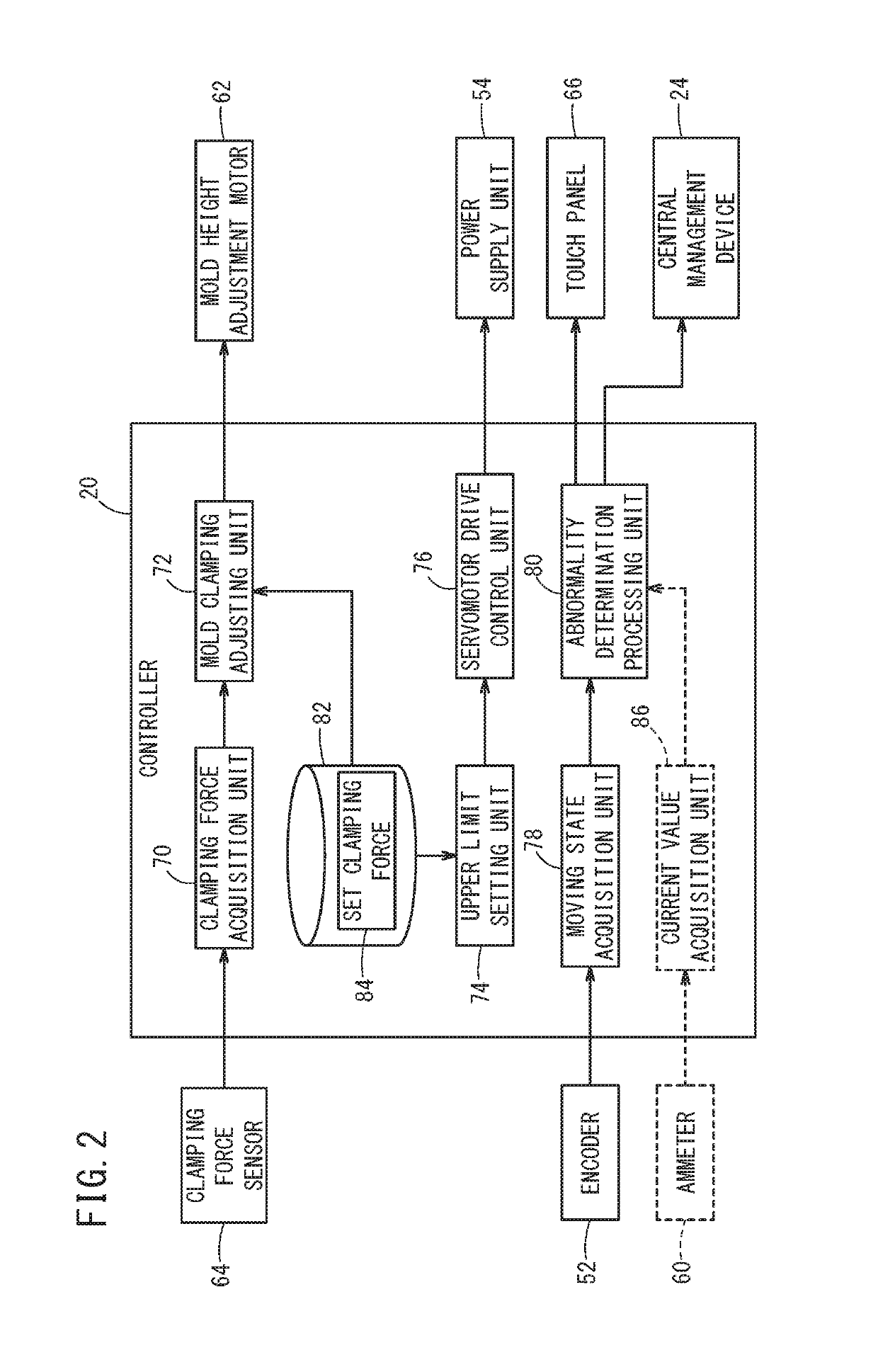
[0091]Specifically, as shown in FIG. 7, the controller 20A according to the second embodiment includes a current value acquisition unit 86 that acquires a detection signal of the ammeter 60, and a threshold storage unit 88 (memory storage area) that stores a current threshold value 88a therein.

[0092]The current value acquisition unit 86 receives a detection signal (driving current v...


PUM

PropertyMeasurementUnit
currentaaaaaaaaaa
clamping forceaaaaaaaaaa
clamping force acquisitionaaaaaaaaaa

Abstract

A controller of an injection molding machine controls mold clamping of a fixed mold and a movable mold. The controller includes a servomotor drive control unit for limiting increase in driving current during driving of a mold clamping servomotor, and a moving state acquisition unit that acquires a detection signal of an encoder. The controller further includes an abnormality determination processing unit for determining that a clamping force sensor is abnormal when recognizing stoppage of movement of the movable mold during mold clamping, based on the acquired detection signal of the encoder.

Description

CROSS-REFERENCE TO RELATED APPLICATION[0001]This application is based upon and claims the benefit of priority from Japanese Patent Application No. 2016-231596 filed on Nov. 29, 2016, the contents of which are incorporated herein by reference.BACKGROUND OF THE INVENTIONField of the Invention[0002]The present invention relates to a controller and a management system for an injection molding machine for clamping a mold.Description of the Related Art[0003]The injection molding machine has an injection mold (made up of a fixed mold and a movable mold) into which a molding material is injected, and performs injection molding by moving the movable mold relative to the fixed mold to thereby bring the molds into contact with each other, and then clamping the molds with a predetermined clamping force. If the clamping force is weaker than the predetermined level, there is a risk of the molding material leaking from the injection mold, burrs occurring in the molded product, etc. Conversely, if ...

Claims


Application Information

Patent Timeline
Patent Type & Authority Patents(United States)
IPC IPC(8): B29C45/76B29C45/66B29C45/17
CPCB29C45/7653B29C45/66B29C45/661B29C2045/1792B29C2045/1794B29C2945/76013B29C2945/76712B29C2945/76083B29C2945/76093B29C2945/76163B29C2945/76234B29C2945/76391B29C2945/76505B29C2945/76033
Inventor NANRI, KODAIMARUYAMA, JUNPEITANAKA, KAZUYOSHI
Owner FANUC LTD
Why Eureka
Try Eureka