Electric connector

a technology of electrical connectors and connectors, applied in the direction of coupling device connections, coupling protective earth/shielding arrangements, electrical apparatus, etc., can solve the problems of adverse influence on the grounding property of the conductive ground shell, and achieve the effect of suppressing the occurrence of electrical loss

Active Publication Date: 2011-06-09
DAIICHI SEIKO CO LTD
View PDF5 Cites 2 Cited by
  • Summary
  • Abstract
  • Description
  • Claims
  • Application Information

AI Technical Summary

Benefits of technology

[0017]As described above, such the electric connector according to the present invention is configured such that the connector-side ground connecting member and the board-side ground connecting member that are provided in the conductive ground shell are disposed such that they extend in approximately in parallel with a fitting direction in which the connector serving as a fitting mate for the electric connector is inserted and approximately in the same direction as the fitting direction, so that a ground current flowing between the connector-side ground connecting member and the board-side gr

Problems solved by technology

As a result, the positional relationship between both the connecting members is such that they are arbitrarily dispersed, therefore there is the possibility that a ground current (an earth current) to be caused to flow between both the connecting members flows towa

Method used


Image

  • Electric connector
  • Electric connector
  • Electric connector

Examples


first embodiment

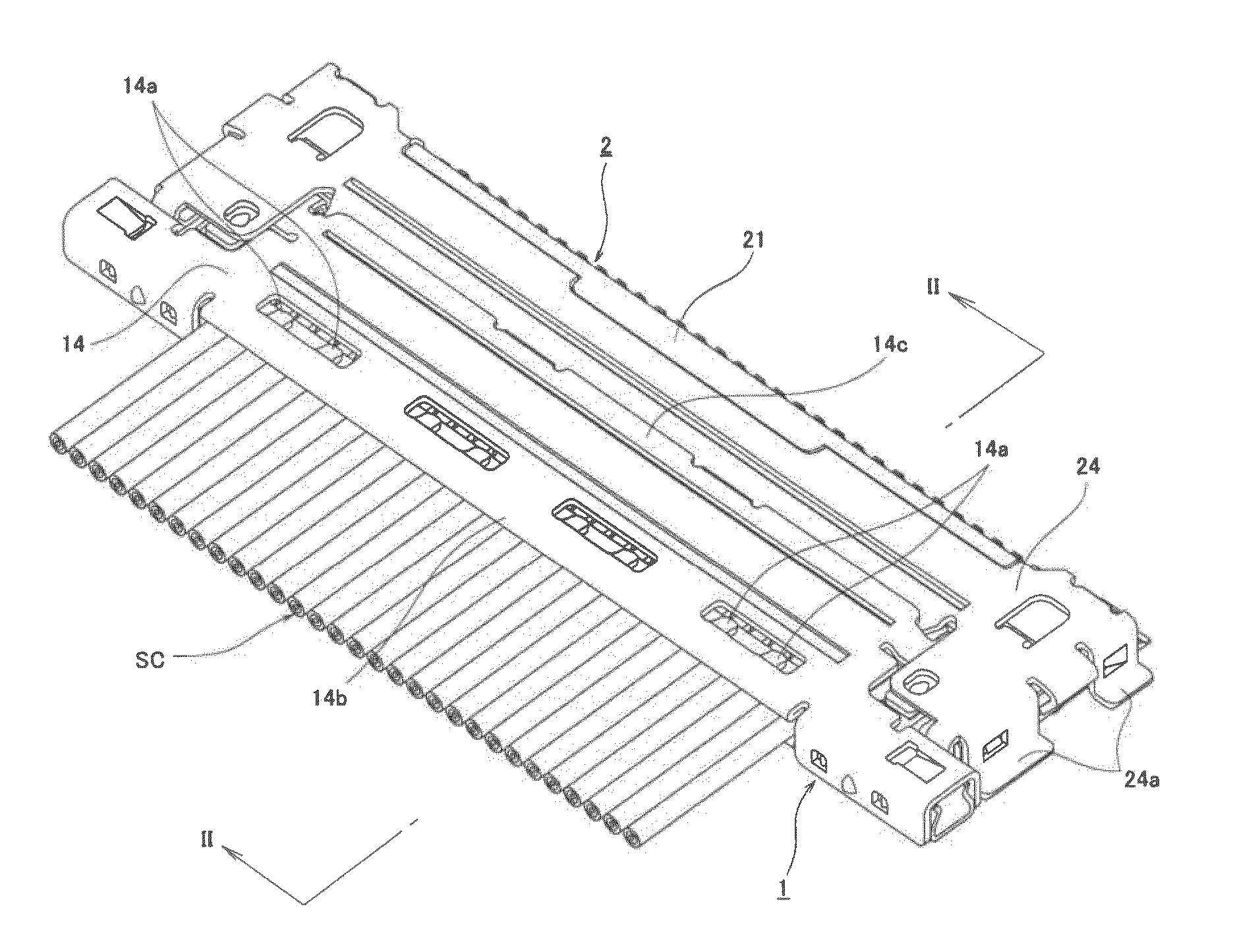
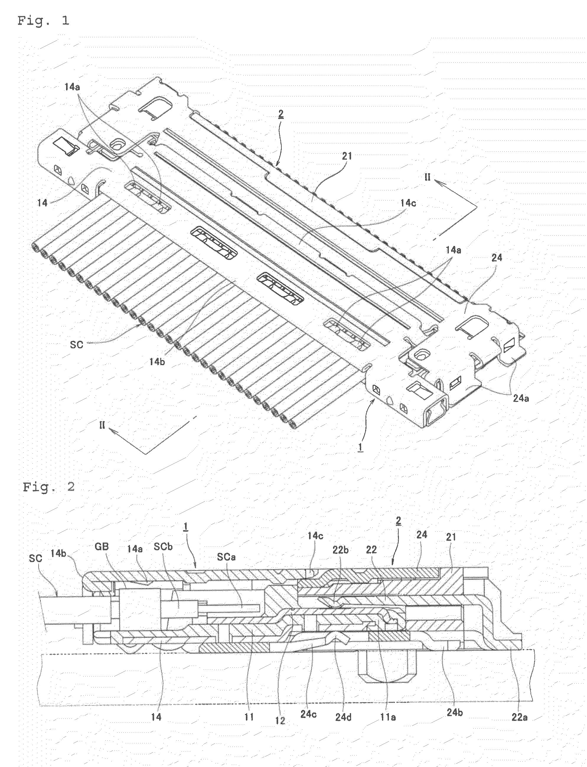
[0029]First, an electric connector assembly according to the present invention shown in FIGS. 1 and 2 is configured as a horizontally-fitting type electric connector comprising a plug connector 1 to which terminal portions of coaxial cables SC are joined and a receptacle connector 2 mounted on a printed wiring board (see the broken lines in FIG. 2). That is, the plug connector 1 which is a connector serving as a fitting mate for the electric connector in the present invention is disposed oppositely and approximately horizontally to the receptacle connector 2 to which the present invention is applied, then the plug connector 1 is moved toward the receptacle connector 2 along a surface of the printed wiring board, a fitting projection 11a provided on a front end portion of the plug connector 1 is inserted into an opening 21b for fitting provided in the receptacle connector 2, thereby both the connectors 1 and 2 are fitted to each other.

[0030]Though, in such a embodiment, as described ...

second embodiment

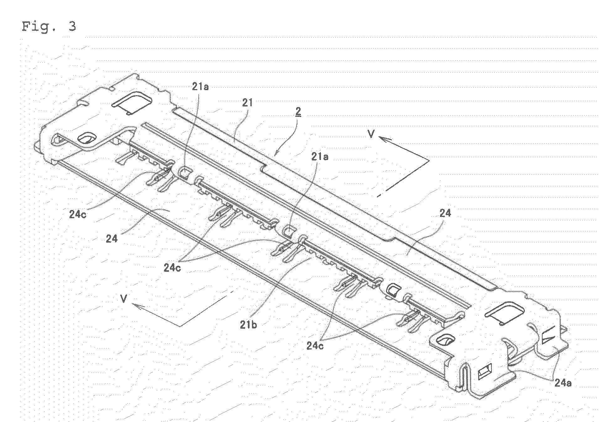
[0066]Then, also in this second embodiment, the respective ground spring pieces (connector-side ground connecting members) 24e and the respective rear holddowns (board-side ground connecting members) 24b are disposed on the same lines extending approximately in parallel with a front-back direction that is the fitting direction of the plug connector 1, and have such a positional relationship that the respective central lines of both the members 24e and 24b extending in the widthwise direction approximately correspond to each other.

[0067]Also in this embodiment having such a configuration, ground currents flowing between the ground spring pieces (connector-side ground connecting members) 24e and the rear holddowns (board-side ground connecting members) 24b take the shortest straight courses, therefore occurrence of electrical loss or an undesired inducing phenomenon are greatly suppressed.

[0068]Hereinbefore, the invention which has been made by the present inventor has been explained ...


PUM


Abstract

To make it possible to improve the grounding property of a conductive shell with a simple configuration.
Connector-side ground connecting members (ground spring pieces) 24c provided in a conductive ground shell 24 of a receptacle connector 2 and board-side ground connecting members (rear holddowns) 24b are disposed such that they extend approximately in parallel with a fitting direction of a plug connector 1 serving as a fitting mate for the receptacle connector 2, and ground currents flowing between the connector-side ground connecting members 24c and the board-side ground connecting members 24b take the shortest straight courses so that occurrence of electrical loss or an undesired inducing phenomenon is substantially suppressed.

Description

BACKGROUND OF THE INVENTION[0001]1. Field of the Invention[0002]The present invention relates to an electric connector configured to be fitted to a connector to perform electrical connection of a signal transmission medium such as a coaxial cable.[0003]2. Description of the Related Art[0004]In a variety of ordinary electrical equipments or the like, an electric connector is widely used for the purpose of connecting a terminal portion of a signal transmission medium comprising a coaxial cable or the like to a printed wiring board. The electric connector comprises, for example, a plug connector to which the signal transmission medium is connected and a receptacle connector mounted on the printed wiring board, and, first, the signal transmission medium such as a coaxial cable is connected to a rear end edge of the plug connector, thereafter, a projection for fitting provided in the plug connector is inserted into an opening for fitting of the receptacle connector, and thus both the con...

Claims


Application Information

Patent Timeline
IPC IPC(8): H01R13/648
CPCH01R12/79H01R13/65802H01R13/6582H01R13/658
Inventor KURACHI, TAKAKI
Owner DAIICHI SEIKO CO LTD
Why Eureka
Try Eureka