
Automatic external cardioverter/defibrillator with tachyarrhythmia detector using a modulation (amplitude and frequency) domain function

a technology of tachyarrhythmia and defibrillator, which is applied in the field of automatic external cardioverter/defibrillator with tachyarrhythmia detector using a modulation domain function, can solve the problems of insufficient algorithms, inability to detect vf, and inherently time-consuming steps, so as to reduce the probability of delivering therapy, reduce the probability of svt event, and increase the probability of shock

Inactive Publication Date: 2001-09-11
ZOLL MEDICAL CORPORATION
View PDF3 Cites 104 Cited by
  • Summary
  • Abstract
  • Description
  • Claims
  • Application Information

AI Technical Summary

Benefits of technology

The therapy delivered by the defibrillator generally includes a series of a predetermined number of defibrillation shocks, delivered at intervals and energy levels that may be individually programmed. At the time a shock is delivered, the defibrillator reconfirm the patient is still in a shockable condition. If the patient is converted, either spontaneously or by other means, to a non-shockable condition, the defibrillator internally disarm the charge and does not deliver the shock to the patient. This feature is called non-committed feature. The defibrillator described in this invention is a non-committed device. Preferably, each shock is synchronized to an intrinsic pulse (R wave), if such a pulse is found within a 2.5 second period. If no intrinsic pulse is detected within that period, then a shock is applied asynchronously. Either defibrillation shocks and anti-tachycardiac therapy may be applied. This automatic synchronization feature eliminates the need for a synchronization button and the need for the operator to select the button position.
Another aspect of the subject device pertains to the method and elements used to detect and confirm the current cardiac rate or rhythm of the patient. Unlike the straightforward average which contains errors from both over-sensing and under-sensing of the QRS's, the concept or the purpose of this method is to reduce effect on the detected heart rate from over-sensing and under-sensing of the QRS's. This invention includes the concept and an implementation of this method. Briefly, the periods between consecutive QRS's obtained from the patient are detected and averaged. The absolute difference between this average and the duration of each of these periods is calculated and the period corresponding to the largest difference is discarded. A new average is then calculated using the remaining periods, the differences are again calculated and the period with the largest difference is again discarded. The current cardiac rate is then determined using the average duration of the remaining periods N-2 where N is the total number of periods in the calculation. In this manner, periods which may have been erroneously sensed due to over- or missed due to under-sensing are eliminated.
The MDF mode is selected to reduce the probability of delivering therapy to SVT's that may be within the preselected rhythm range, without compromising the sensitivity of the ventricular tachyarrhythnia therapy. As the cardiac rate increases the probability of an SVT event is reduced and the probability that a shock is required increases. The MDF is designed to differentiate between the two (ventricular tachycardia VT and SVT) conditions in the overlapping cardiac rate range.

Problems solved by technology

All these steps are inherently time-consuming.
However, the algorithms used by these defibrillators to detect VF are very limited.
Obviously, these algorithms are not satisfactory since it is important to detect when those conditions happen and apply therapy as soon as those conditions are detected.

Method used


Image

  • Automatic external cardioverter/defibrillator with tachyarrhythmia detector using a modulation (amplitude and frequency) domain function
  • Automatic external cardioverter/defibrillator with tachyarrhythmia detector using a modulation (amplitude and frequency) domain function
  • Automatic external cardioverter/defibrillator with tachyarrhythmia detector using a modulation (amplitude and frequency) domain function

Examples


Embodiment Construction

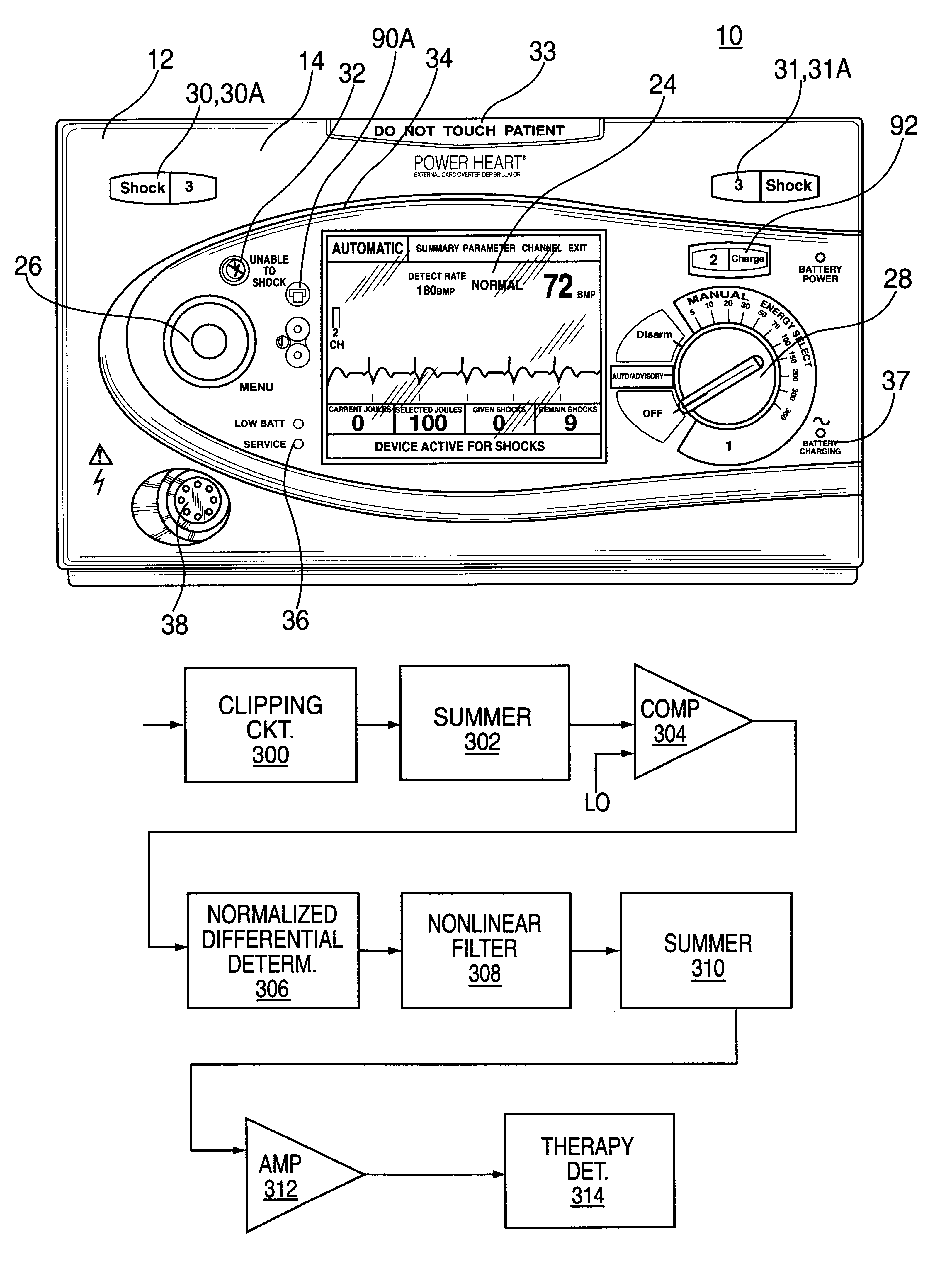
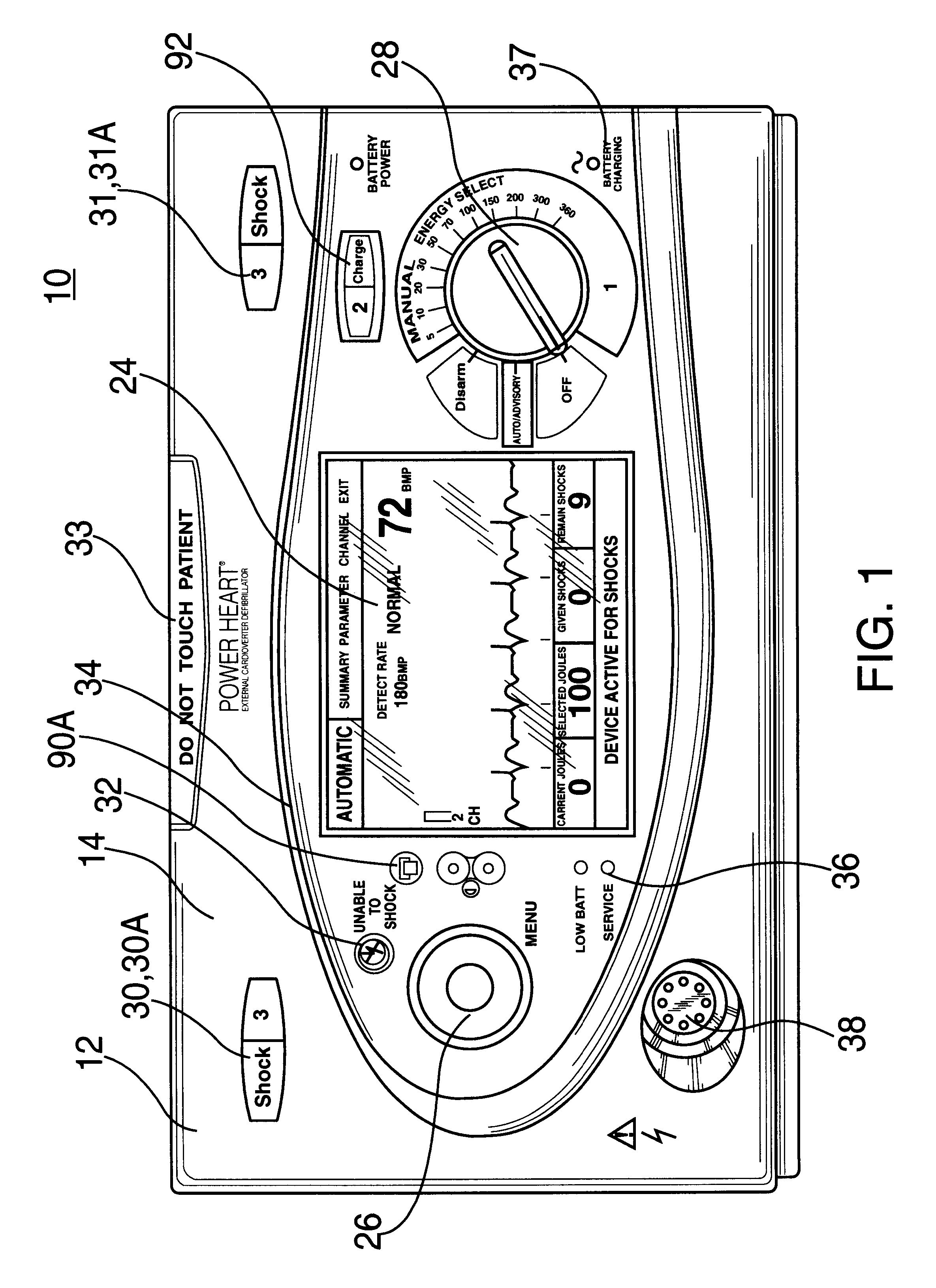
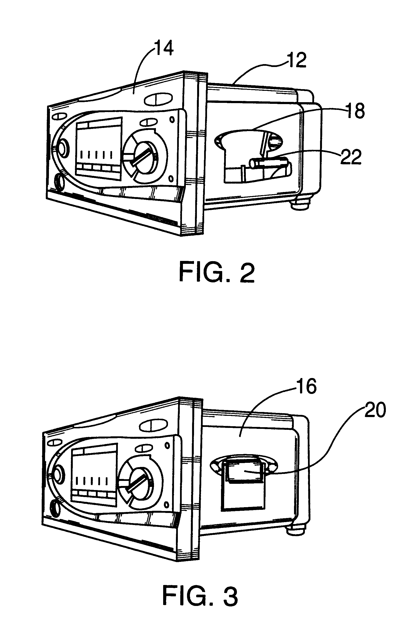
FIG. 1 shows a defibrillator 10 having a housing 12 with a front face 14 on which a plurality of controls and indicating elements are provided, as described in more detail below. The defibrillator further includes electrode assembly shown in FIG. 4 and described in detail below. As seen in FIGS. 2 and 3, one side 16 of the housing 12 is provided with a cavity 18. A printer (not shown) is mounted in cavity 18. A roll of paper 20 is mounted on shaft 22 in a manner which allows the printer to print alphanumeric characters and graphics on paper 20.

The housing 12 can be positioned on a rack, or other support means so that it can be disposed adjacent to the patient.

Referring back to FIG. 1, a screen display 24 is mounted on the front face 14 so that it is clearly visible. The display is used to provide information to the clinician related to the operation of the defibrillator 10, the status of the patient, etc. Disposed around the display 24, there are other indicator and control elements...


PUM


Abstract

An external defibrillator includes a detector used to detect a life threatening condition of a patient, a controller operating the defibrillator automatically and a therapy delivery circuit that delivers appropriate therapy. Advantageously a parameter is derived from the cardiac signals sensed in the patient, the parameters being used to differentiate between shockable events such as ventricular tachyarrhythmia and other events such as SVT. The defibrillator is attached to a patient by an attendant and once it is attached, the defibrillator is adapted to monitor the patient and when a life threatening condition is detected, to apply therapy automatically, i.e., without any involvement by the patient or the attendant.

Description

BACKGROUND OF THE INVENTIONA. Field of InventionThis invention pertains to an external defibrillator arranged and constructed to provide anti-tachyarrhythmia therapy to a patient on demand. In particular, an automatic external cardioverter / defibrillator is described which has several operational modes including a fully automatic mode in which shocks are delivered without any manual intervention, an advisory mode and a manual mode. Moreover, the invention pertains to a defibrillator with an integral tachyarrhythmia detector which detects an abnormal heart beat and determines whether this abnormal heart beat is amenable to shock therapy.B. Description of the Prior ArtDefibrillators are devices which apply electric therapy to cardiac patients having an abnormally high heart rhythm. Two kinds of defibrillators are presently available: internal defibrillators which are implanted subcutaneously in a patient together with leads extending through the veins into the cardiac chambers, and ext...

Claims


Application Information

Patent Timeline
IPC IPC(8): A61B5/0464A61B5/0452A61N1/39A61B5/024A61B5/0245A61B5/363
CPCA61N1/39A61N1/3925A61N1/3993A61N1/3904
Inventor LIN, DONGPINGYBARRA, RAULMATHUR, PRABODH
Owner ZOLL MEDICAL CORPORATION
Learn More