Hub arrangement for a hydrodynamic torque converter and method for producing same

Inactive Publication Date: 2001-09-18
ZF FRIEDRICHSHAFEN AG
View PDF8 Cites 10 Cited by
  • Summary
  • Abstract
  • Description
  • Claims
  • Application Information

AI Technical Summary

Benefits of technology

Because the hub arrangement is made of two parts, it is possible to prepare the fluid channel arrangement in a simple manner in that the recess arrangement is provided during the manufacture of the individual hub components. The fluid channel arrangement is then finally completed when the hub arrangement is assembled by the two hub components resting against one another. According to this embodiment of the present invention, no drilling processes or other work processes are required subsequent to the assembly of the hub arrangement to generate the different fluid channels or fluid channel arrangement in the hub component.
The hub arrangement according to the present invention may be produced in a particularly simple manner when a recess arrangement is formed only at one of the surface regions located opposite one another. In this embodiment, the first and the second hub components are structural component parts which are essentially symmetric with respect to rotation. Therefore, there is no need to ensure that the two hub components are in a predetermined rotational position relative to one another when connecting them.
In this embodiment, it is particularly advantageous for technical reasons relating to manufacture when a recess arrangement is formed only in the first hub component in the region of the cup-shaped recess. Therefore, the fitting projection or the fitting element does not require a recess arrangement.
In this way, a channel configuration is achieved in which a first channel area extends substantially radially, i.e., the substantially radially extending fluid channel area provided in the component, and a second channel area which adjoins each substantially radially extending fluid channel and which extends approximately axially. Accordingly, the arrangement of inclined channel areas according to the prior art, which can only be incorporated with difficulty, are not required and may be omitted. The channel configuration including the first channel area that extends radially and the second channel area that extends axially is arranged to ensure that the different fluid channels open only relatively close to the axis of rotation in their radial inner region, so that fluid turbulence can be extensively prevented in this fluid area.
The hub arrangement produced according to the above process does not require inclined bore holes that are difficult to produce. Therefore, this complicated step of producing inclines bore holes may be eliminated.
In this procedure, when providing groove-shaped recesses on the fitting element in the area of the cup-shaped recess, the hub component itself is not required to have groove-shaped recesses. This is especially advantageous when the hub component is produced by a forging process.

Problems solved by technology

The fluid channels 32' are relatively difficult to produce, which results in complicated and cost-intensive production processes.
Accordingly, it is not possible to construct these fluid channels such that they extend substantially radially, namely, in the area of the hub arrangement formed by approximately annular walls.

Method used


Image

  • Hub arrangement for a hydrodynamic torque converter and method for producing same
  • Hub arrangement for a hydrodynamic torque converter and method for producing same
  • Hub arrangement for a hydrodynamic torque converter and method for producing same

Examples


embodiment form

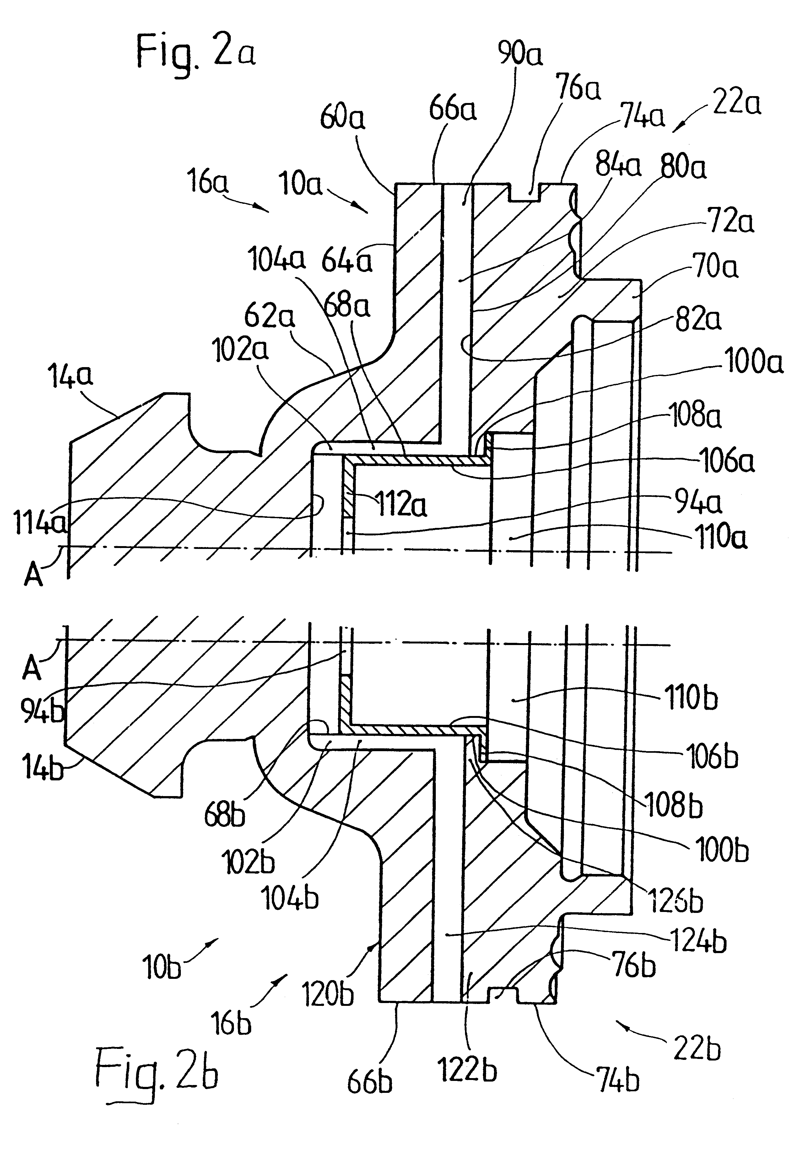
the hub arrangement 10b may, for example, be provided by first producing a forging blank with the channels 124b produced there, e.g., by drilling, and with the groove-shaped recesses 102b machined, for example, by forging or broaching. In this embodiment, the extension of the flange-like area 108b of the fitting piece 106b is preferably greater in the radial direction than in the previous embodiments because the opening 110b is also correspondingly enlarged radially thereby allowing the groove-shaped recess 102b to be made by broaching.

After the forging blank has been provided with the different channels or channel portions, it can be finish-machined by turning, so that it is put into a form suitable for use. The fitting piece 106b may then be pressed in, as was described above, to close, in the radial inner direction, the groove-shaped recesses 102b for forming the channel portions 104b.

The embodiment of FIG. 2b also circumvents the introduction of diagonal bore holes in the hub ar...


PUM

PropertyMeasurementUnit
Shapeaaaaaaaaaa
Areaaaaaaaaaaa

Abstract

A hub arrangement for a hydrodynamic torque converter includes a first hub component forming a first hub area with a first connection area connectable with a converter housing of the torque converter, a second hub component forming a second hub area with a second connection area connectable with a lockup clutch of the torque converter, and a fluid channel arrangement having at least one fluid channel connecting a radial inner area of the hub arrangement with a radial outer area. The first hub component and the second hub component contact one another at least in some areas in surface regions thereof which are located opposite one another. A recess arrangement is arranged in at least one of the oppositely located surface regions of the first and second hub components for forming the fluid channel arrangement.

Description

1. Field of the InventionThe present invention is directed to a hub arrangement for a hydrodynamic torque converter including a first hub area with a first connection area for connecting with a converter housing, a second hub area with a second connection area for connecting with a component of a lockup clutch of the torque converter, and a fluid channel arrangement with at least one fluid channel which connects a radial inner area of the hub arrangement with a radial outer area of the hub arrangement and which opens outward in the radial outer area in the direction of a hub rotational axis between the first hub area and the second hub area.2. Description of the Related ArtA hub arrangement having a first hub area and a second hub area with a fluid channel arrangement connecting a radial inner area to a radial outer area of the hub arrangement is known, for example, from German Reference DE 44 23 640 A1. FIG. 3 of the present application shows a torque converter provided with the kn...

Claims


Application Information

Patent Timeline
IPC IPC(8): F16H45/02F16H45/00F16H41/00F16H41/30
CPCF16H41/30F16H45/02Y10T29/4933F16H2045/0278
Inventor BECHMANN, DIETRICHHEGEL, THOMASWOHNER, GUNTERMEYER, ANDREILLIG, ROLAND
Owner ZF FRIEDRICHSHAFEN AG
Why Eureka
Try Eureka