Electric dry razor

a dry shaver and electric technology, applied in the direction of metal working devices, etc., can solve the problem of cumbersome cleaning and more complicated cleaning

Inactive Publication Date: 2001-10-16
PAYER ELECKTROPRODUKTE GMBH +1
View PDF10 Cites 78 Cited by
  • Summary
  • Abstract
  • Description
  • Claims
  • Application Information

AI Technical Summary

Problems solved by technology

In such configurations clea...

Method used


Image

  • Electric dry razor
  • Electric dry razor
  • Electric dry razor

Examples


Embodiment Construction

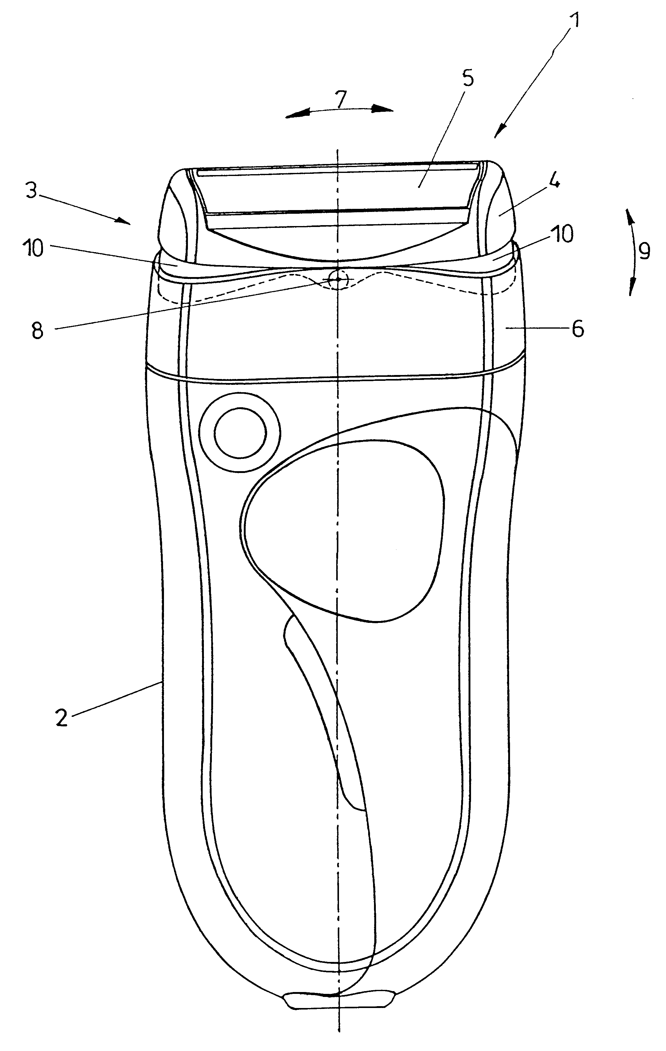
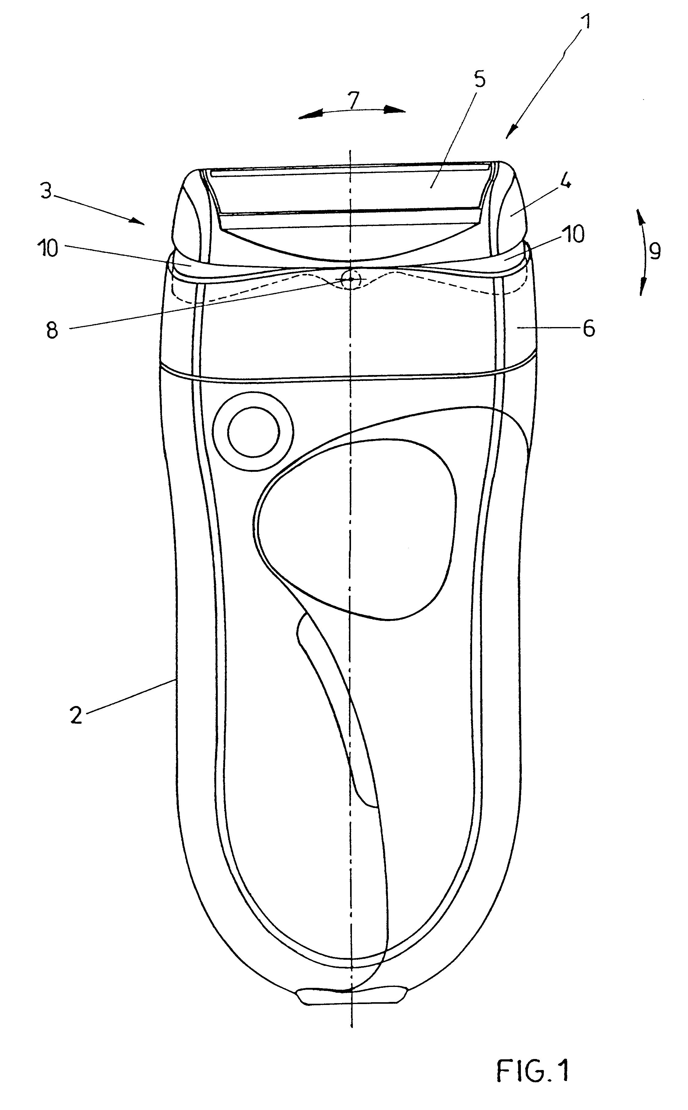
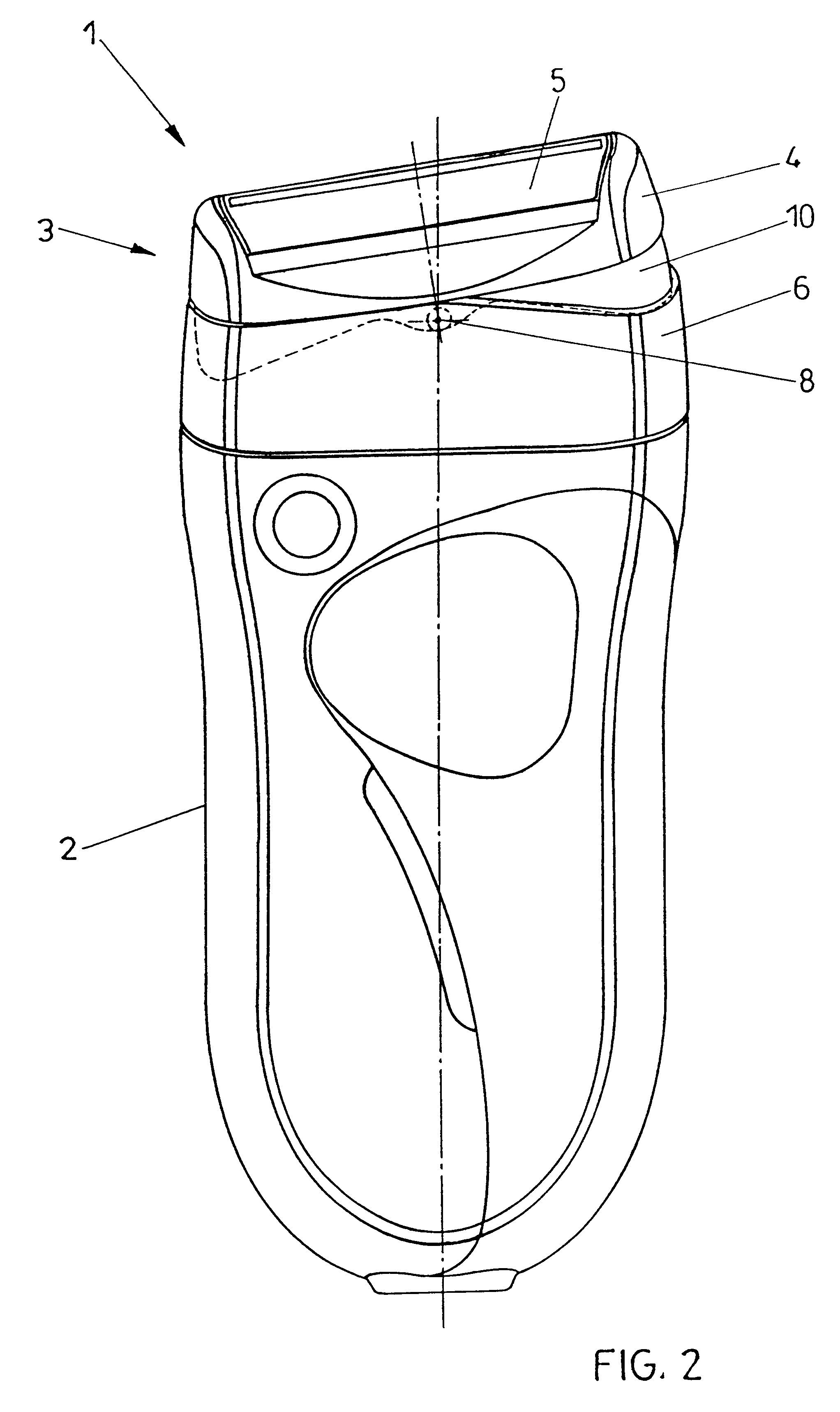
FIG. 1 depicts a dry shaver 1 comprising a base part 2 as well as a head frame 3. The head frame 3, which is designed in two parts, comprises an outer head part 4 accommodating the shaving blades 5 as well as a head part 6 which is detachably fixed to the base part 2. The shaving blades 5 arranged in the outer head part cooperate with cutter blades or lamellae not illustrated in detail, the cutter blades or lamellae oscillating in the direction of the double arrow 7. The outer head part 4 is connected with the head part 6 detachably fixed to the base part 2, so as to be pivotable about a pivot axis 8 extending transverse to the oscillation direction 7 of the cutter blades or lamellae. Thus, the pivotability of the outer head part 4 comprising the shaving blades 5 is ensured in the direction of the double arrow 9, thereby enabling the outer head part comprising the shaving blades 5 to by optimally adapted to the contour of the skin. The outer head part 4 comprises sealing surfaces 10...


PUM


Abstract

A dry shaver includes at least one shaving blade which is arranged in a pivotable head frame closed on its sides and which cooperates with cutters oscillating in the longitudinal direction of the shaving blades. The head frame is detachably connected with a base part which includes a cutter driving mechanism. The head frame is designed in two parts, wherein an outer head part carrying the shaving blade(s) is pivotally connected with a part of the head frame that is detachably fixed to the base part, the pivotal connection being about an approximately central pivot axis extending transverse to the oscillation direction of the cutters.

Description

1. Field of the InventionThe invention relates to a dry shaver including at least one shaving blade which is arranged in a pivotable head frame closed on its sides and cooperates with cutters oscillating in the longitudinal direction of the shaving blades, wherein the shaver head is detachably connected with the base part including the driving mechanism.2. Prior ArtDry shavers are known in various configurations. Besides dry shavers comprising rotating cutters, in which the shaving blades having relatively small diameters are resiliently arranged in a head frame, dry shavers are above all known, in which a driving motor is arranged in a base part and coupled with one or several cutter blade blocks or lamella carriers, whereby the lamellae or cutter blades of the cutter blade blocks or lamella carriers are set in an oscillating movement. The direction of oscillation of such cutter blade blocks extends in the direction of the axis of the enveloping curve of the lamellae, wherein said ...

Claims


Application Information

Patent Timeline
IPC IPC(8): B26B19/04
CPCB26B19/048B26B19/04
Inventor OSWALD, MATHIASPIRMAYER, OTTO
Owner PAYER ELECKTROPRODUKTE GMBH
Why Eureka
Try Eureka