Digital speed determination in ultrasonic flow measurements

a technology of ultrasonic flow and speed determination, applied in the direction of fluid speed measurement, instruments, measurement devices, etc., can solve the problems of difficulty in accurately estimating the arrival of the wave, and difficulty in adjusting the zero-crossing method

Inactive Publication Date: 2001-10-23
COMMONWEALTH SCI & IND RES ORG
View PDF10 Cites 55 Cited by
  • Summary
  • Abstract
  • Description
  • Claims
  • Application Information

AI Technical Summary

Problems solved by technology

This method has several difficulties.
The condition where two peaks within the wavepacket are identical in magnitude is one which the zero-crossing method finds particularly difficult to accommodate.
The accuracy of the timing of the arrival of the wave is usually limited to one clock pulse, this time interval therefore represents the uncertainty of the measurement.

Method used


Image

  • Digital speed determination in ultrasonic flow measurements
  • Digital speed determination in ultrasonic flow measurements
  • Digital speed determination in ultrasonic flow measurements

Examples


Embodiment Construction

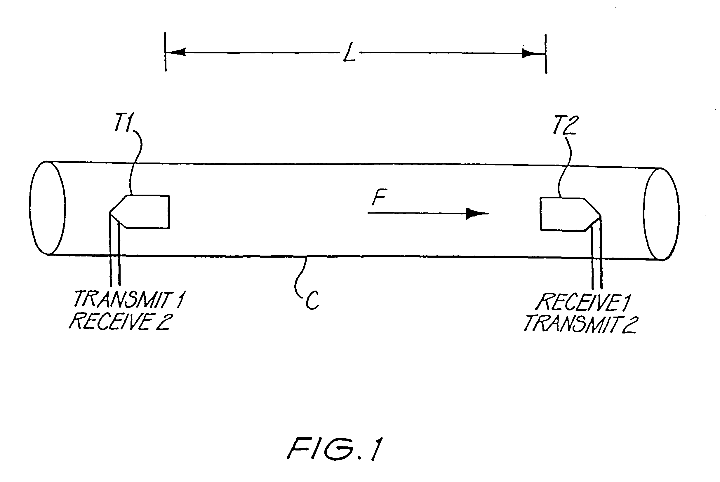
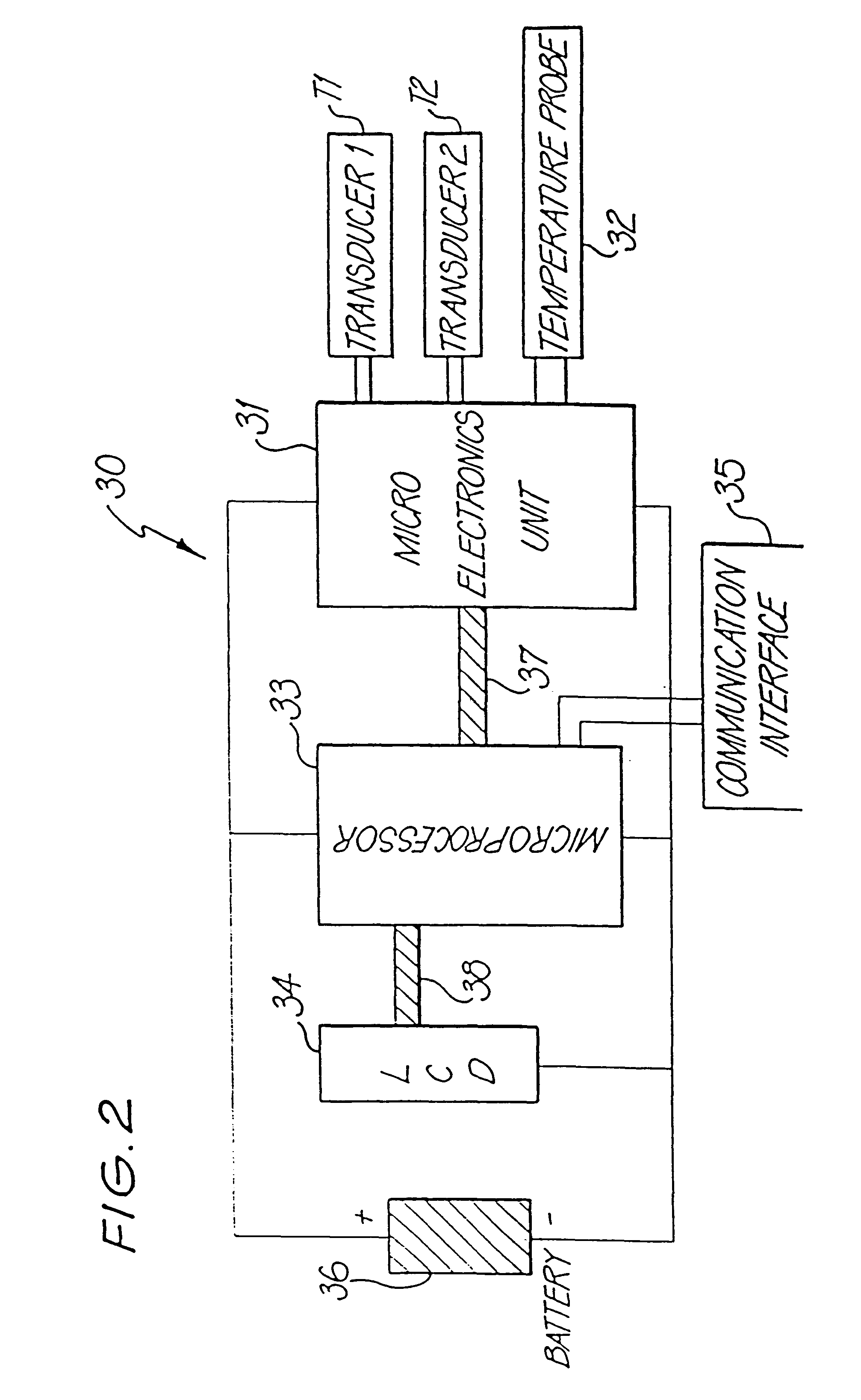
FIG. 1 shows two ultrasonic transducers, T1 and T2, each of which can act as either a transmitter or a receiver, disposed facing each other along the axis of a cylindrical measurement chamber C and separate by a length L through which a fluid F, whose flow velocity .nu. is to be measured, is flowing. The measurement chamber C is part of an overall measurement circuit 30 represented schematically in FIG. 2.

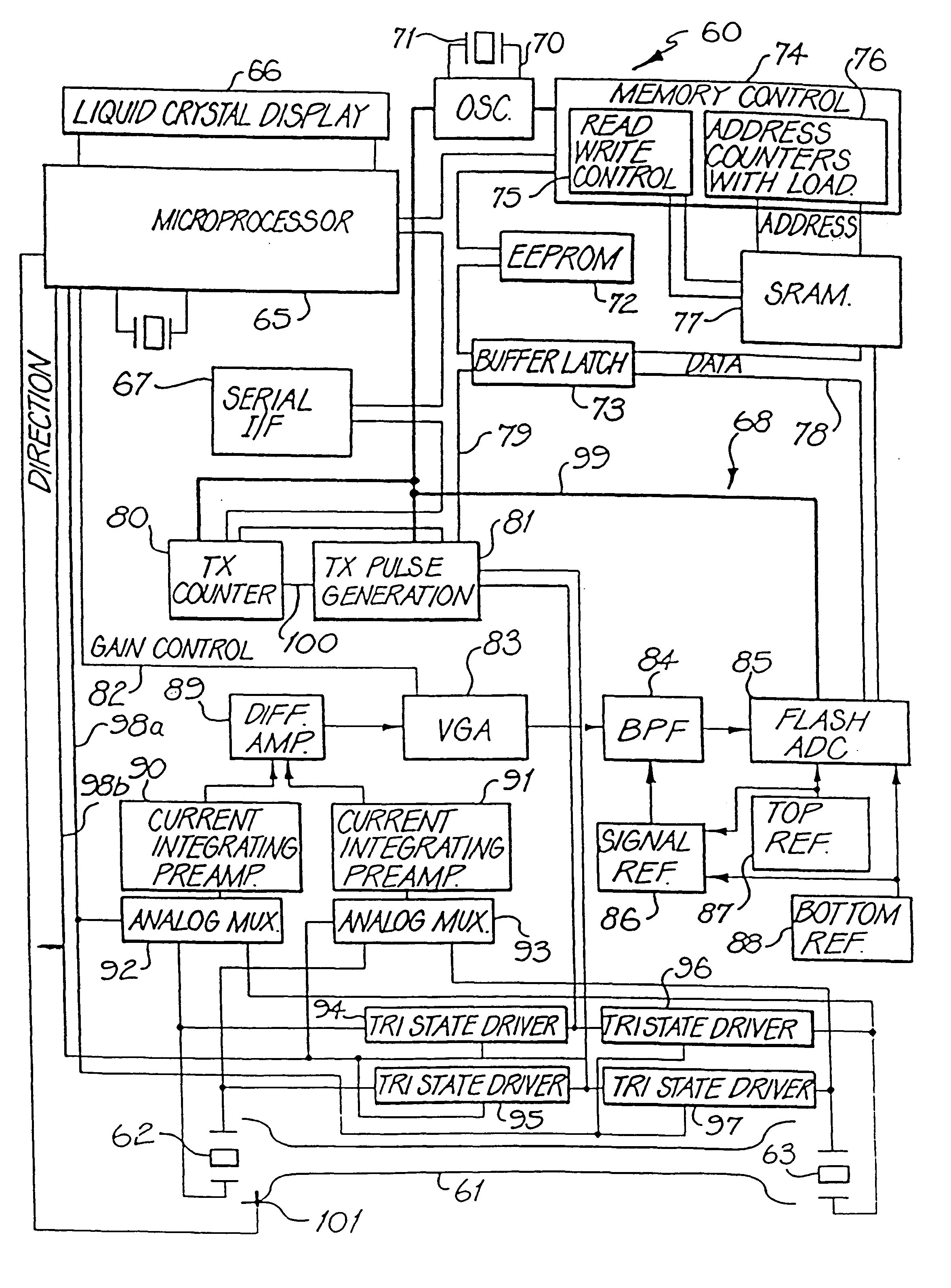
The measurement system 30 includes a controlling microprocessor 33 linked via a main bus 37 to a microelectronics unit 31 which contains specialist electronics that interconnect to the transducers T1 and T2, and to a temperature probe 32, positionable within the measurement chamber C to determine the temperature of the fluid F whose flow is being measured. A battery unit 36 supplies electrical energy to the microprocessor 33 and microelectronics unit 31, the latter of the two generating signals for and receiving signals from the transducers T1 and T2, and determining individual tim...


PUM


Abstract

A method and device (60) is described which measures the speed of a flowing fluid (F) by measuring the difference in time taken for an ultrasonic signal to travel first upstream and then downstream in the fluid. In each direction the device (60) calculates the time taken for an ultrasonic wave packet emitted by one ultrasonic transducer (62) to be received by another (63). The method used consists of the digitisation (85) of the received waveform and the subsequent identification of waveform features by comparison with a standard template of the waveform. The position in time of these features is then determined with respect to a high speed clock (70). The results are then used in a weighted computation to determine the time of arrival of the waveform at the transducer (63).

Description

The present invention relates to a device for measuring the flow speed of a moving fluid and which utilizes ultrasonics and digital speed determination.DESCRIPTION OF THE RELATED ARTThe measurement of the difference in propagation time for the upstream and downstream travel of an ultrasonic signal in a moving fluid is an established method used to measure the rate of flow of that fluid. The ultrasonic signal used for such purposes typically consists of a wave packet of sinusoidal shape with peaks of differing amplitudes. An example of such a wave packet is depicted in FIG. 3 which shows an electronically received ultrasonic signal 40. The problem of accurately determining the time of arrival of such a signal is generally considered to involve two specific criteria.The first is the unique identification of a particular part of the received signal 40 that can be used as a timing reference. The part usually chosen is a point at which one cycle of the wave crosses the signal axis 42, a ...

Claims


Application Information

Patent Timeline
Patent Type & Authority Patents(United States)
IPC IPC(8): G01F1/66G01P5/24G01P5/00G01S7/523G01S7/527
CPCG01F1/667G01P5/245G01S7/527G01F1/66
Inventor BRAATHEN, COLIN WALTERBIGNELL, NOELWELSH, CHARLES MALCOLMBESLEY, LAURENCE MICHAEL
Owner COMMONWEALTH SCI & IND RES ORG
Why Eureka
Try Eureka