
Base plate for mounting router in a support table

a router and support table technology, applied in the field of work benches, can solve the problems of inconvenient fastening method, inability to mount routers in the support table, and the damage of fasteners in such materials is relatively rapid, so as to prevent excessive wear and damage, and maintain configurational integrity.

Inactive Publication Date: 2001-10-23
ROUSSEAU TONY
View PDF16 Cites 74 Cited by
  • Summary
  • Abstract
  • Description
  • Claims
  • Application Information

AI Technical Summary

Benefits of technology

A further object is to provide such a support plate that has a slightly raised medial portion spacedly adjacent the cutter orifice defined therein to compensate for wear and assure that the supporting area about the cutter is no lower than the support table surface about the base plate.
A still further object is to provide such a base plate that is formed of a strong, rigid and durable polymeric or resinousness plastic to prevent excessive wear, damage from impact and pressure type intrusive forces and to maintain configurational integrity to a substantially greater extent than traditional wood or wood-like support tables.
A still further object is to provide such a base plate that is of new and novel design, of rugged and durable nature, of simple and economic manufacture and one otherwise well adapted for the uses and purposes for which is intended.

Problems solved by technology

Though these supports have had substantial historicity and during their historical period have become increasingly sophisticated, problems still remain with their use.
This method of fastening is inconvenient in general and especially when the tool base plate must be removed and replaced frequently, as is commonly the case.
Additionally, support tables commonly are formed of wood or derivatives having similar properties and the use of either bolt or screw type fasteners in such material is fairly rapidly destructive of the fastening areas, so as not to allow frequent fastening and unfastening and soon make such fastening less secure, even if operative.
Another problem often presented by a tool carrying base plate, and especially those used with routers, is that the base plate surface closely adjacent to the cutting tool extending therethrough may be lower than the upper surface of the surrounding support table, even though the periphery of the base plate is coplanar with the upper surface of the support table.
The condition of either base plate or support table may change with use and wear, and commonly, the base plate surface closely adjacent to the cutting tool may be worn and abraded by use to a greater extent than more distal areas to become lower than the surface of the support table.

Method used


Image

  • Base plate for mounting router in a support table
  • Base plate for mounting router in a support table
  • Base plate for mounting router in a support table

Examples


Embodiment Construction

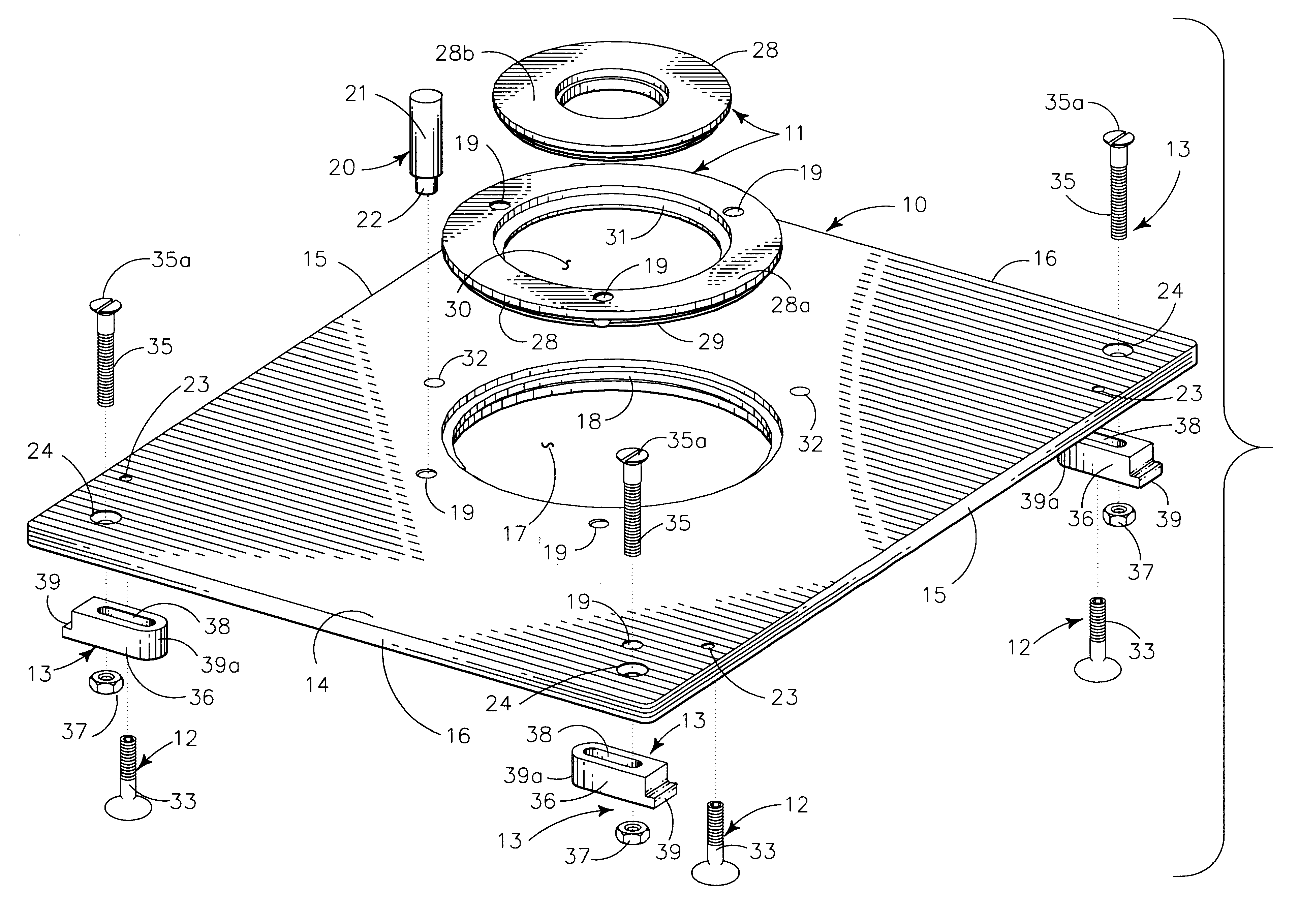
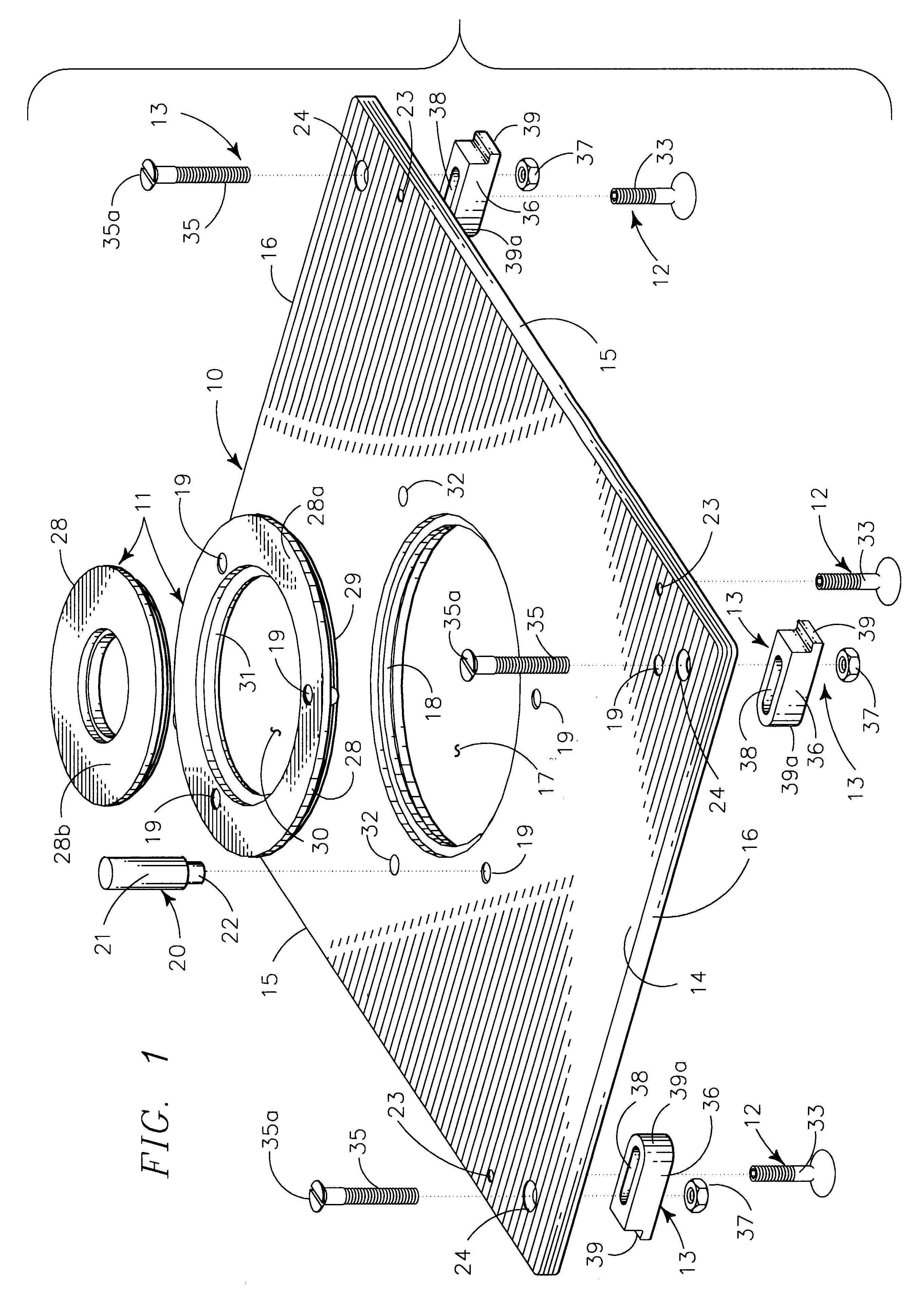
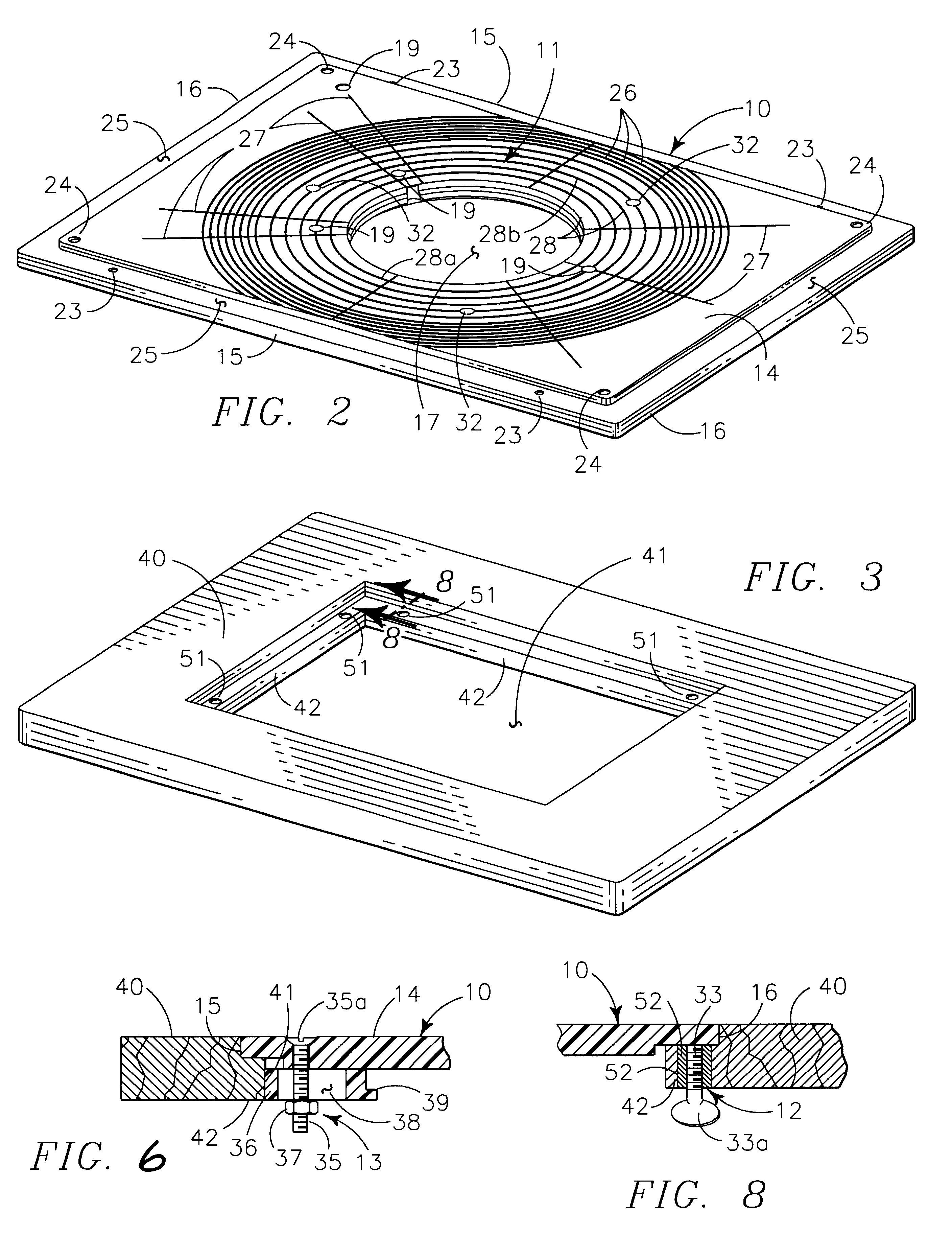
As seen in FIG. 1 the instant mounting structure provides base plate 10 defining a medial orifice carrying plural inserts 11 and having plural levelers 12 and corner fasteners arrayed 13 about the peripheral edges.

Base plate 10 in the instance illustrated provides rigid flat substantially planar plate 14 defined by similar longer sides 15 and shorter ends 16, the upper edges of which are coplanar. The illustrated generally rectilinear peripheral configuration of the plate 14 is not essential and other peripheral configurations are within the ambit and scope of my base plate, though the rectilinear configuration illustrated, or one of similar geometry, generally make more simple the formation of an orifice in a support table to receive the base plate. The entire upper surface of the plate 14 may be coplanar, but preferably is formed as a portion of a truncated right circular cone having a very shallow side slope of approximately one degree to provide a raised medial portion of the up...


PUM


Abstract

A base plate for mounting a router in a support table provides a plate configured to fit in an orifice, having an inwardly extending ledge thereabout, defined in the support table with the router supported by the base plate to depend therefrom. The base plate defines a medial orifice for passage of the router shaft through the orifice for operative positioning of a cutter carried on the router shaft above the base plate. The base plate medial orifice releasably carries plural annular inserts to cover space between the router shaft and the support plate portion defining the medial orifice. Plural adjustment screws are carried in threaded engagement in the ledge of the support surface orifice for vertical motion to adjustably move adjacent portions of the base plate periphery upwardly from the ledge to create a coplanar relationship of adjacent portions of the base plate and support table. The base plate carries at least one releasably adjustable fastener to fasten the support plate on the ledge in the orifice defined in the support table.

Description

BACKGROUND OF INVENTION1. Related ApplicationsThere are no applications related hereto heretofore filed in this or any foreign country.2. Field of InventionThis invention relates generally to workbenches and more particularly to a workbench defining a medial orifice to releaseably carry a base plate supporting a depending router with the router blade in operative position above the support table.BACKGROUND AND DESCRIPTION OF PRIOR ARTWith the advent and development of modern powered hand tools of substantial sophistication, it has become popular to operatively support those tools in or on some type of table-like support to provide more functional utility that often approaches the functional utility of a large stationary tool of the same type, but with substantially less overall costs. Various of such supports have become known and provided for handsaws, drills, planers, routers and the like and some such supports have become known to service more than a single type of such tools. Th...

Claims


Application Information

Patent Timeline
Patent Type & Authority Patents(United States)
IPC IPC(8): B27C5/00B27C5/02B27C5/10
CPCB27C5/02B27C5/10
Inventor ROUSSEAU, TONY
Owner ROUSSEAU TONY
Learn More