Hydraulic grain storage bin lifting system and method

Inactive Publication Date: 2001-11-06
BAINTER WESLEY ALLEN
View PDF11 Cites 52 Cited by
  • Summary
  • Abstract
  • Description
  • Claims
  • Application Information

AI Technical Summary

Problems solved by technology

Although the process for building a grain bin may seem simple, building a grain bin using present methods is really quite difficult and labor intensive.
The most difficult part of bin construction is raising the successive circular rings of panels so that all parts of the structure stay level and lift at the same rate.
If this is not done properly, parts of the structure will be overloaded and will fail.
Such incremental o

Method used


Image

  • Hydraulic grain storage bin lifting system and method
  • Hydraulic grain storage bin lifting system and method
  • Hydraulic grain storage bin lifting system and method

Examples


Embodiment Construction

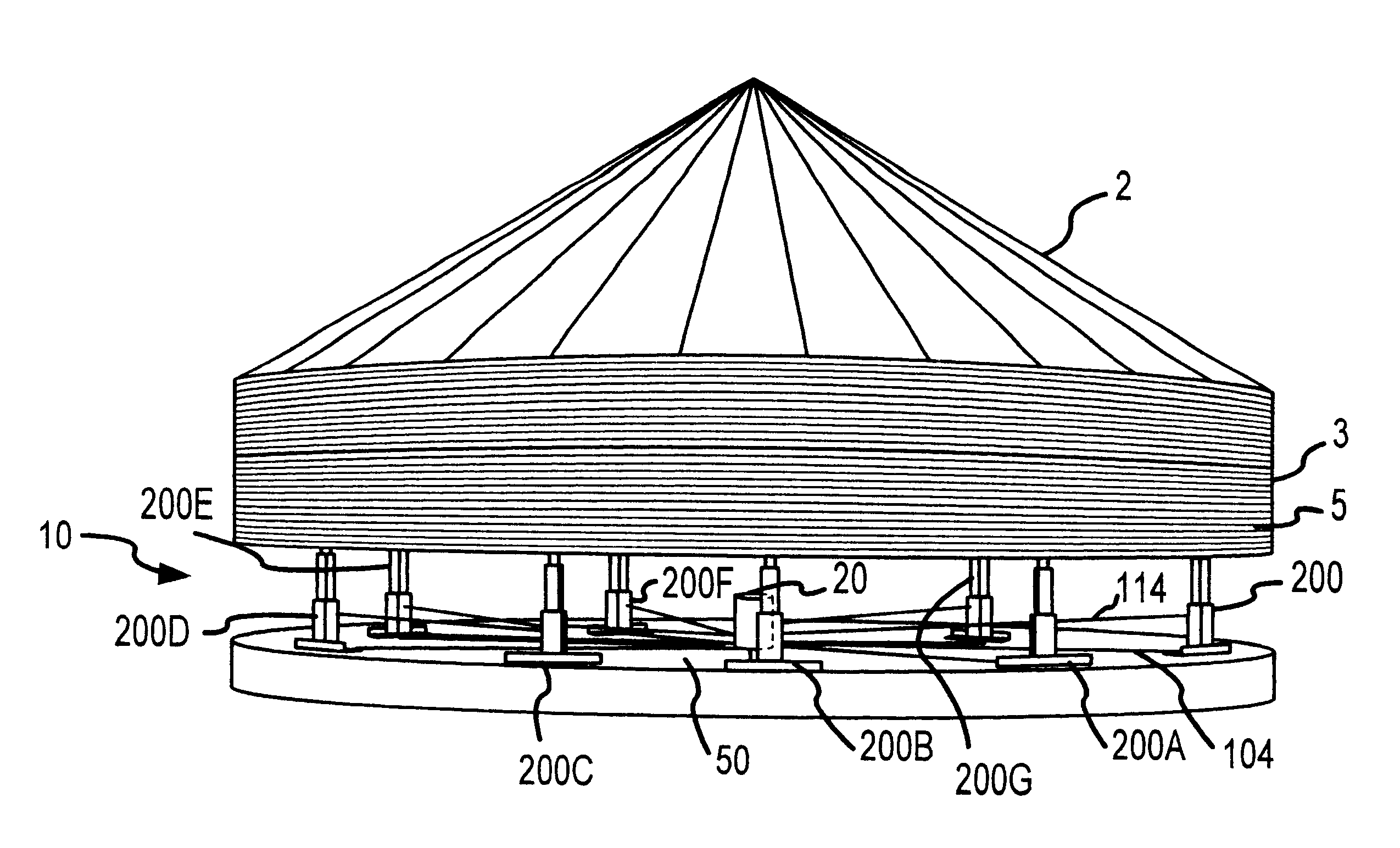
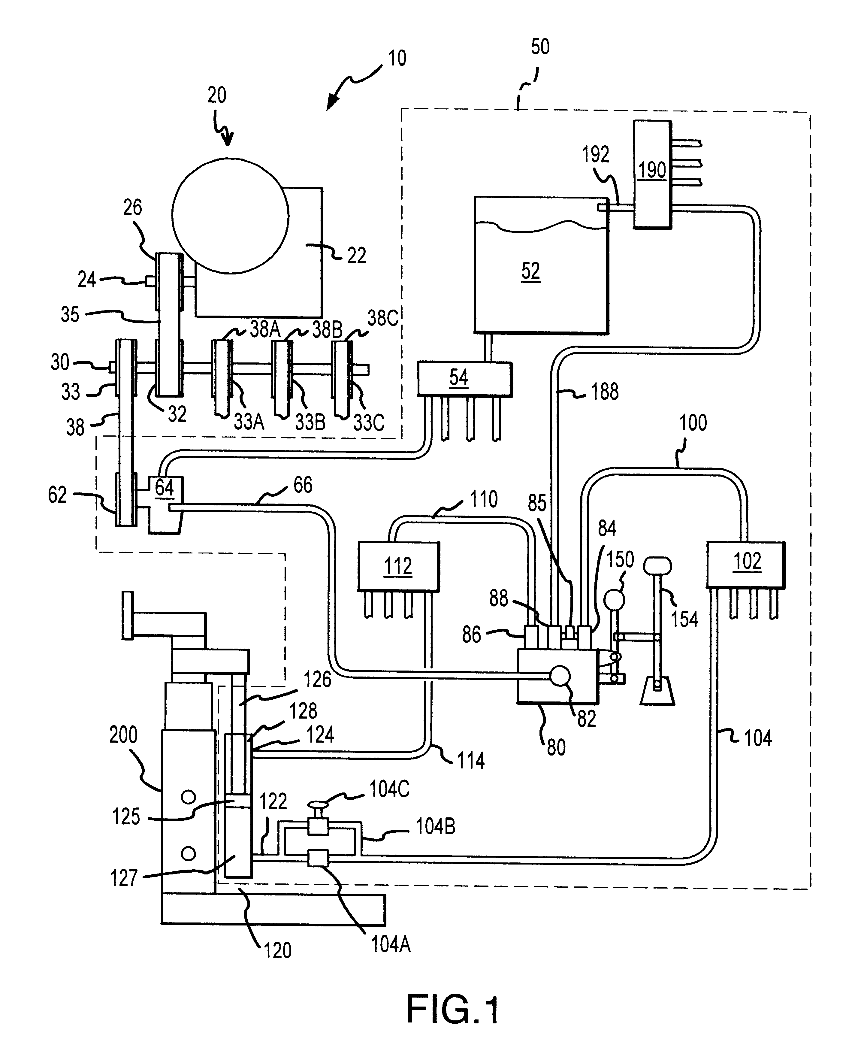
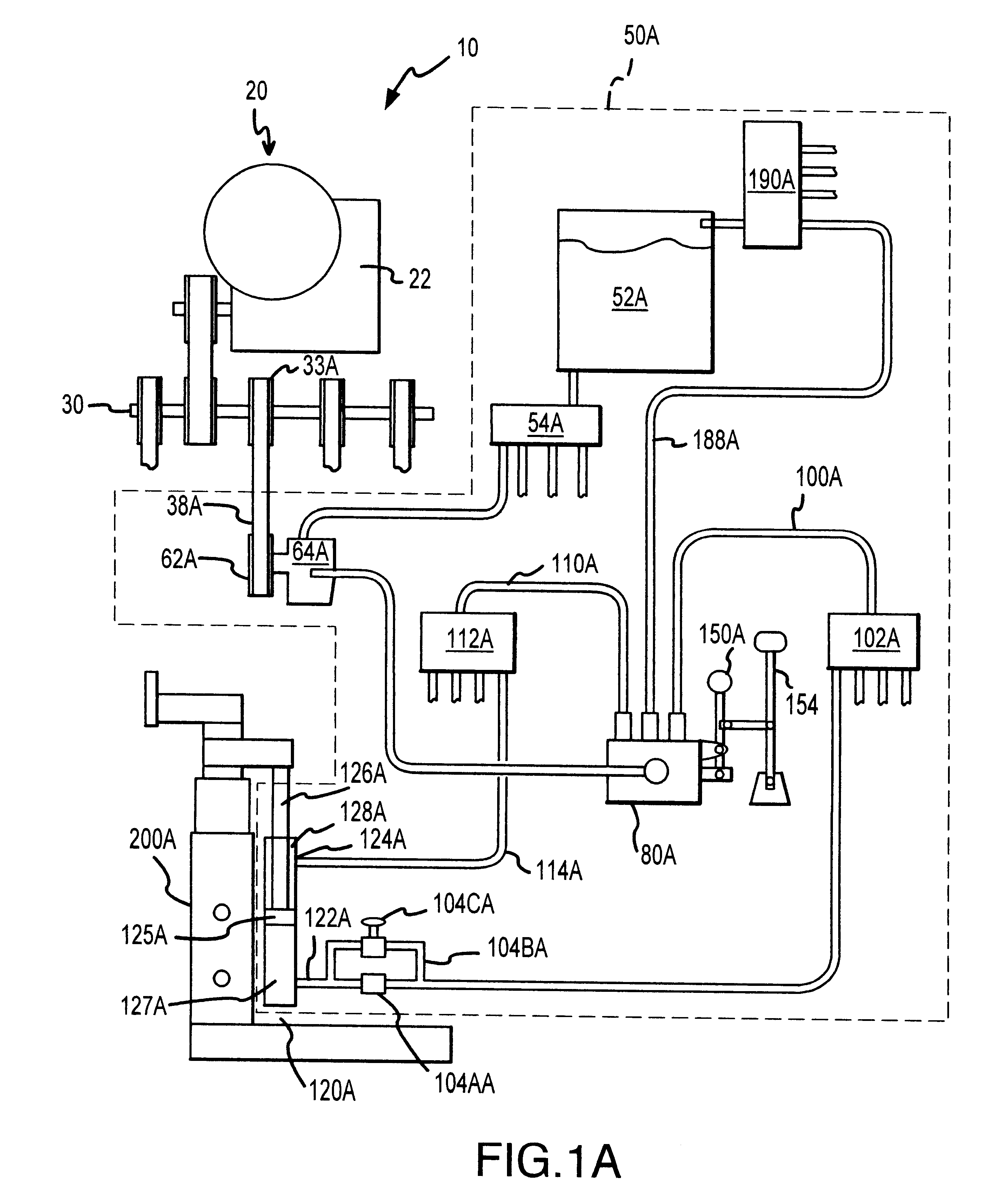
The basic purpose of invention lifting system 10 is to raise a structure evenly using a number of hydraulic jacks served by several hydraulic circuits which are in turn powered by one power source. The invention lifting system 10 is schematically illustrated in FIG. 1. Generally, the lifting system 10 includes a drive system 20, hydraulic circuits such as hydraulic circuit 50 and jacks such as jack 200. Generally drive system 20 includes a power source 22, and an arrangement of timing belts and timing pulleys for driving, at the same rate, a set of four hydraulic pumps identical to positive displacement hydraulic pump 64. Hydraulic circuit 50 shown in FIG. 1 and its duplicate, hydraulic circuit 50A shown in FIG. 1A and two other companion hydraulic circuits (not shown) are powered by identical positive displacement pumps 64 and 64A respectively and two other identical companion pumps (not shown). Drive system 20 drives all four of these pumps.

Hydraulic circuit 50 shown in FIG. 1 inc...


PUM


Abstract

The present invention is a method for constructing cylindrical grain bins. The method employs a sets of identical, telescoping jacks actuated by hydraulic cylinders and an hydraulic system having separate hydraulic circuits that serve each set of jacks. Using the set of identical, hydraulic, telescoping jacks, successive rings of a grain bin structure made up of connected panels are lifted. After a first ring is lifted, a second ring can be attached to the lower edge of the first ring. The second ring is then lifted and the process is repeated until the grain bin is completed.

Description

1. Field of the InventionThe present invention relates to a method and apparatus for lifting successive rings of corrugated steel panels to construct cylindrical grain bins.2. Background of the InventionModem grain bins typically have cylindrical steel walls and conical steel roofs assembled from prefabricated components. The cylindrical steel wall of a modem grain bin is fashioned from curved steel panels having horizontal corrugations. Bolt holes are located about the edges of the curved steel panels so that panels can be fastened to the lower edge of an assembled roof and to each other in successive rings to complete a bin. Accordingly, the present method for assembling a grain bin generally includes the following steps: (a) laying a concrete foundation, (b) constructing a circular roof, (c) lifting the roof, (c) attaching a first ring of panels, (d) raising the roof and the first ring of panels, (e) attaching a second ring of panels to the first ring, and (f) attaching successiv...

Claims


Application Information

Patent Timeline
IPC IPC(8): B66F7/20B66F3/24B66F3/28B66F7/10E04B1/35E04H7/30E04H7/00
CPCB66F3/28B66F7/20E04B1/3522E04H7/30B66F3/46Y02A40/51
Inventor BAINTER, WESLEY ALLEN
Owner BAINTER WESLEY ALLEN
Why Eureka
Try Eureka