Sanding machine

a sanding machine and sanding wheel technology, which is applied in the direction of grinding machines, grinding/polishing apparatuses, manufacturing tools, etc., can solve the problems of high cost, insufficient health care of workers using this type of equipment, and large wear and tear of the inner portion of the sanding machin

Inactive Publication Date: 2001-11-13
GHILARDI PIERANGELO
View PDF12 Cites 26 Cited by
  • Summary
  • Abstract
  • Description
  • Claims
  • Application Information

AI Technical Summary

Problems solved by technology

These arrangements were very inefficient, costly and did not fully address the health concerns of the workers using this type of equipment.
It moves freely up and down the outer periphery of the body of the abrasive member and consequently incurs substantially more wear and tear than the inner portion.
Although this configuration prevents less damage to the main sander body, it does not capture any more debris than a normal suction head.
Although this process decreases the likelihood of foreign matter igniting the contents of the collection bag, it does not filter out the smaller debris which escape into the air during the sanding process.
However, the major drawback is the intense degradation which the shaft casing encounters during the sanding process.
Although the increased suction surface area allows a wider area for collection, it results in diminishing suction capacity because the finer debris accumulates inside the motor and air lines causing the air volume to be reduced.
This system also results in diminishing suction capacity due to the accumulation of finer debris.
Currently, sanding machines are not capable of maintaining the high level of suction capacity required to capture accumulated debris.
The lungs of the operator are damaged by the fine debris and dust generated by the sanding process.
Even if the operator wears a filtration device, it can not trap all of the finer debris.
In many cases, the operator does not wear such a device because it inhibits the efficiency of his work by limiting his vision and distorting his perception.
It not only effects the lungs but can damage the eyes, inner ear and nasal passages and cause severe skin irritation disorders.
Not only does this shorten the life of the machine, and the cost of replacement and maintenance, but it makes the operation of this high-powered suction device more dangerous.

Method used


Image

  • Sanding machine
  • Sanding machine
  • Sanding machine

Examples


Embodiment Construction

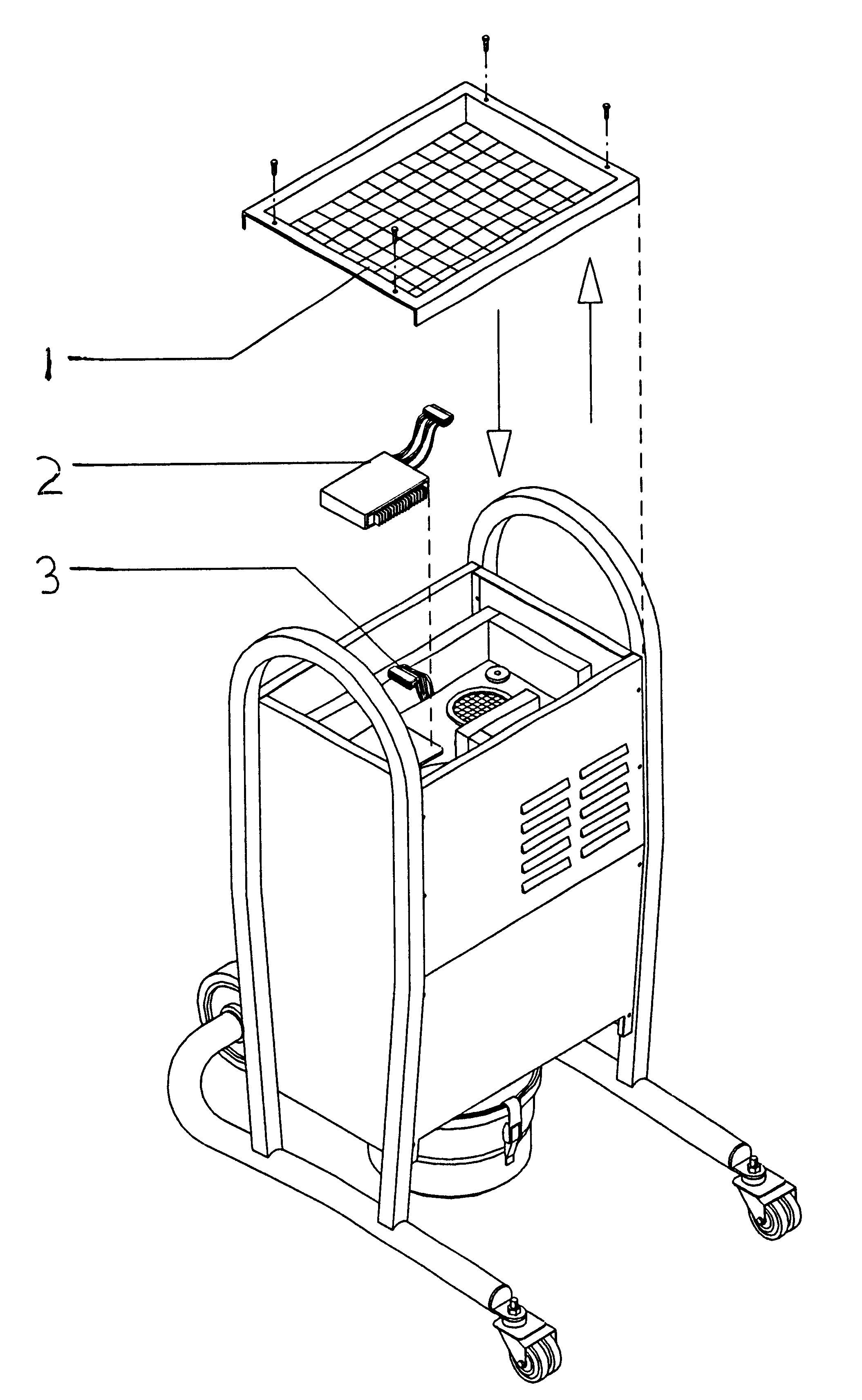
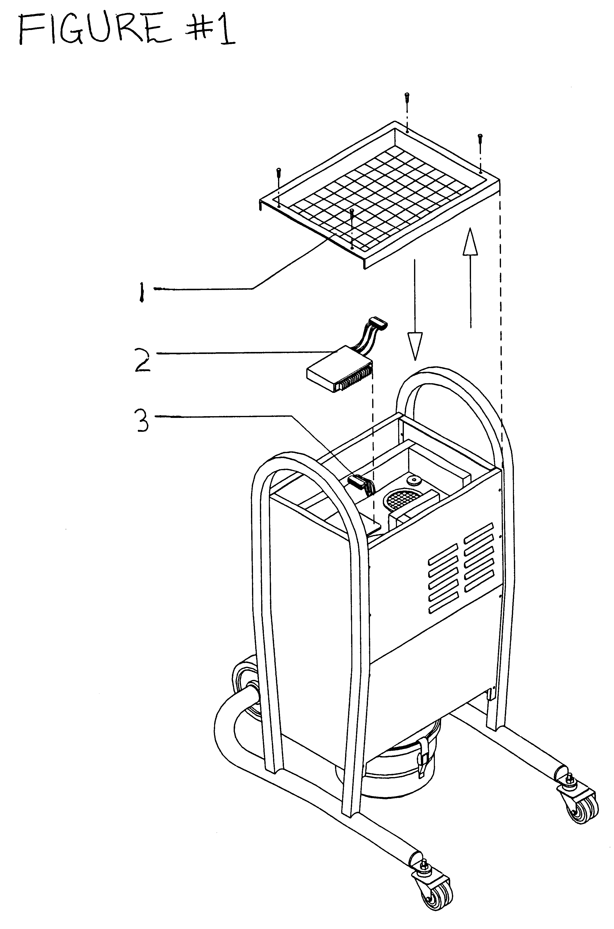
Operation of my invention is simple and straightforward. A base-unit houses three motors which power the driver cable to rotate the sanding head, provide suction to suck the debris back into the base unit adhering it to the cleaning cylinders and electro-magnetically stimulate the cleaning cylinders causing them to release the debris downward into a collection receptacle. A single hose houses both the driver cable, used to turn the sanding head, and a pathway for the debris to be sucked back into the base unit. The driver cable is additionally encased in a protective sheath containing a self-lubricating liquid to prevent damage to the driver cable and sheath and also prevents contamination of the debris with the driver cable.

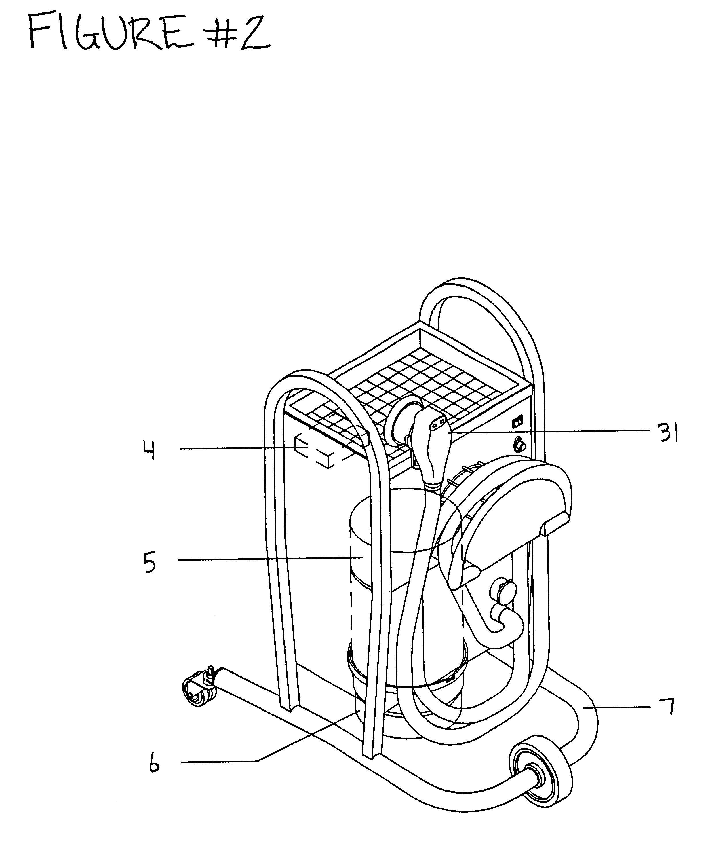
In FIG. 1, the top cover, 1, is lifted off to reveal the top of the base unit. The electronic power box, 2, sits directly underneath the cover, 1, next to the driver cable motor, and is connected to the three motors by a connector receptor, 3. In FIG. 2, the col...


PUM


Abstract

A sanding machine with a hand-held sanding unit, with interchangeable heads, connected to a base unit, containing three motors, one to provide suction of debris back through a hose, which has an inner hose containing a driver cable and self lubricating material, which allows the transportation of debris back to the base unit collection unit, connecting the base unit and hand-held unit, a second motor to power a driver cable which turns the hand-held unit, a third motor which is encased inside a collection unit, inside the base unit, which generates electromagnetic vibrations causing filters to release accumulated debris by the interaction of an inner and outer spring.

Description

1. Field of InventionThis invention relates to a portable sanding machine which contains three motors which provide suction to remove debris, elect-magnetic vibrations to cleanse the filter springs and gyration to turn a driver cable and generate the spinning action of the abrasive head. This head is connected to the base unit via a hose which simultaneously transports the debris to a collection unit and houses a separate self-contained hose, containing lubrication, in which a driver cable is enclosed to turn the abrasive head.2. Description of Prior ArtHeretofore many different arrangements were used to collect debris generated during the sanding process. These arrangements were very inefficient, costly and did not fully address the health concerns of the workers using this type of equipment. It is important to collect as much debris as possible, generated by the sanding process, so that it can not be breathed in by the user.One arrangement which focuses upon the issue of improved ...

Claims


Application Information

Patent Timeline
Patent Type & Authority Patents(United States)
IPC IPC(8): B24B23/02B24B23/00B24B55/00B24B55/10
CPCB24B23/02B24B55/102
Inventor GHILARDI, PIERANGELO
Owner GHILARDI PIERANGELO
Why Eureka
Try Eureka