System for forming dental impressions

a technology for dental impressions and impression caps, applied in the field of dental impression systems, can solve the problems of improper lingual representation and unfavorable patient comfort, and achieve the effects of low cost, convenient use and effective

Inactive Publication Date: 2001-11-20
MAYWEATHER GEORGE S
View PDF2 Cites 30 Cited by
  • Summary
  • Abstract
  • Description
  • Claims
  • Application Information

AI Technical Summary

Benefits of technology

The present invention relates to a system which provides an easy to use, effective means for eliminating the problems noted above. The invention is characterized by its simplicity and its relatively low cost.

Problems solved by technology

Lower dental impression trays typically define a lingual recess to accommodate a patient's tongue during the taking of an impression and it is not uncommon for the plaster or other casting material to flow over the tray and into the lingual recess, resulting in an unsightly appearance and improper lingual representation.

Method used


Image

  • System for forming dental impressions
  • System for forming dental impressions
  • System for forming dental impressions

Examples


Embodiment Construction

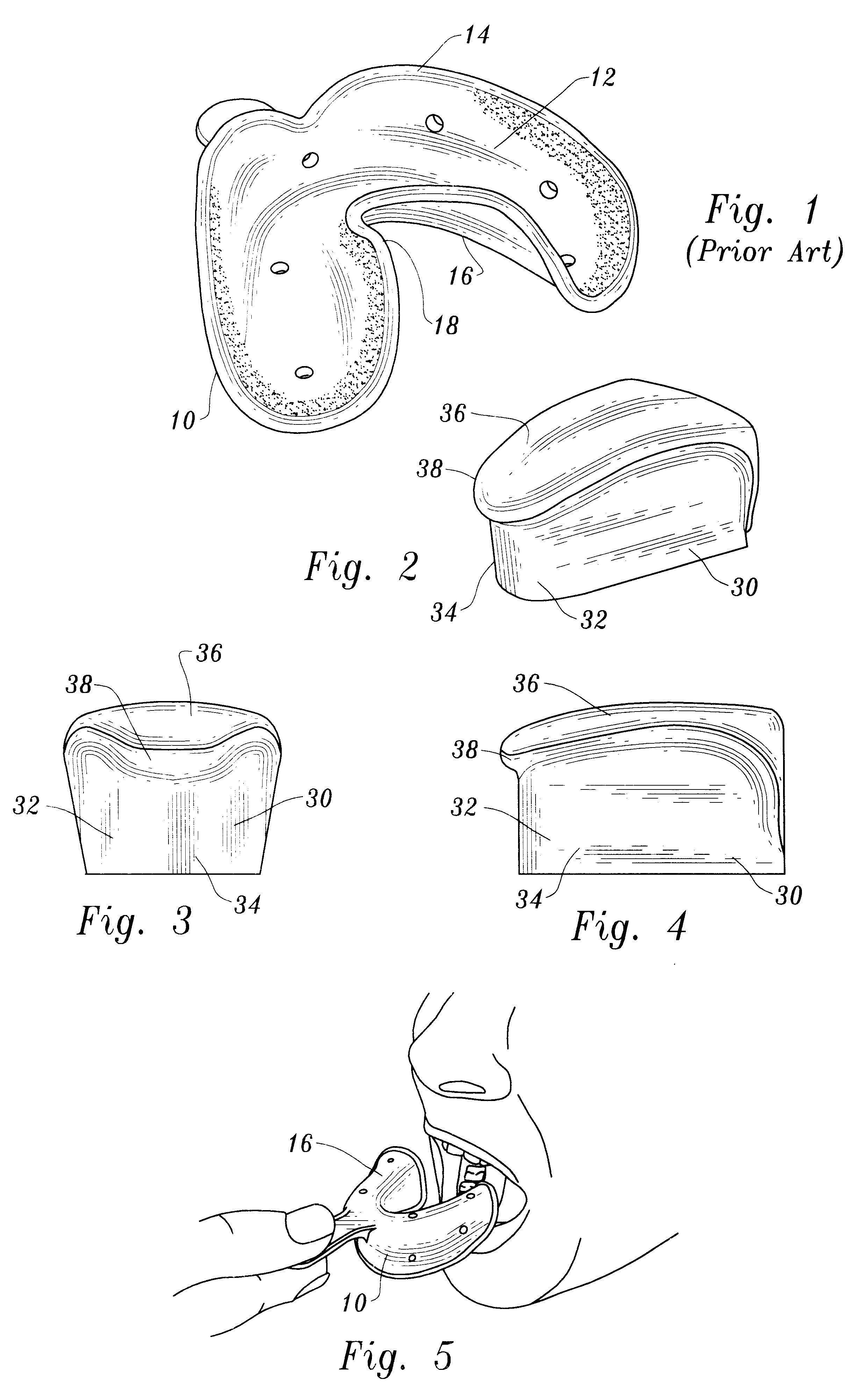
FIG. 1 illustrates a conventional dental impression tray utilized to take dental impressions. The dental tray is designated by reference number 10. The dental impression tray is typically constructed of plastic or metal material and includes a tray interior 12, a tray top 14 and a tray bottom 16. The tray 10 includes a tray portion defining a tray recess 18 for accommodating an individual's tongue when taking an impression.

FIG. 5 illustrates the tray being inserted into a patients mouth. In the figure, the tray has been inverted so that the tray bottom 16 is disposed upwardly. It will be appreciated that the tray interior accommodates a teeth impression material such as wax.

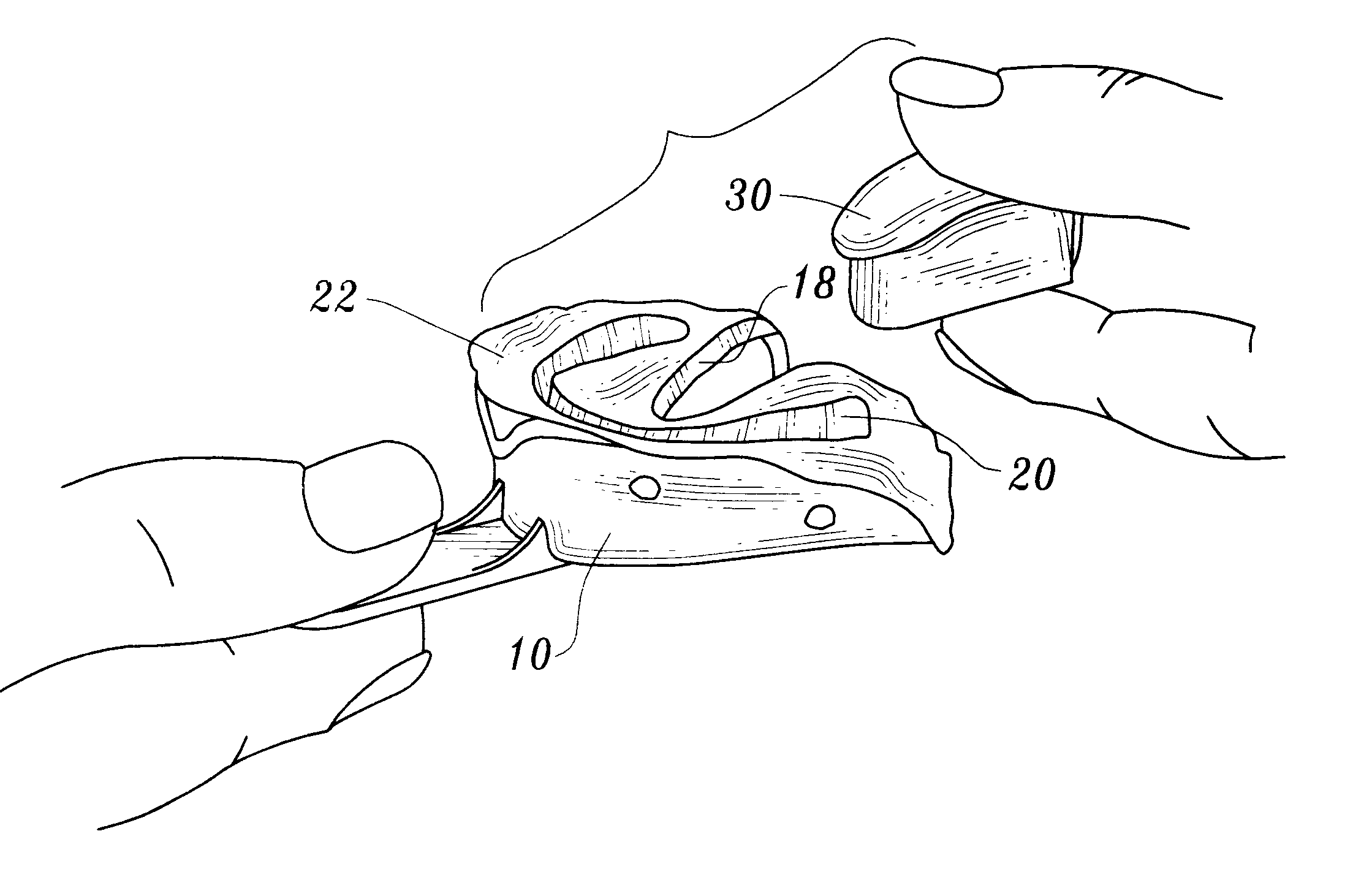
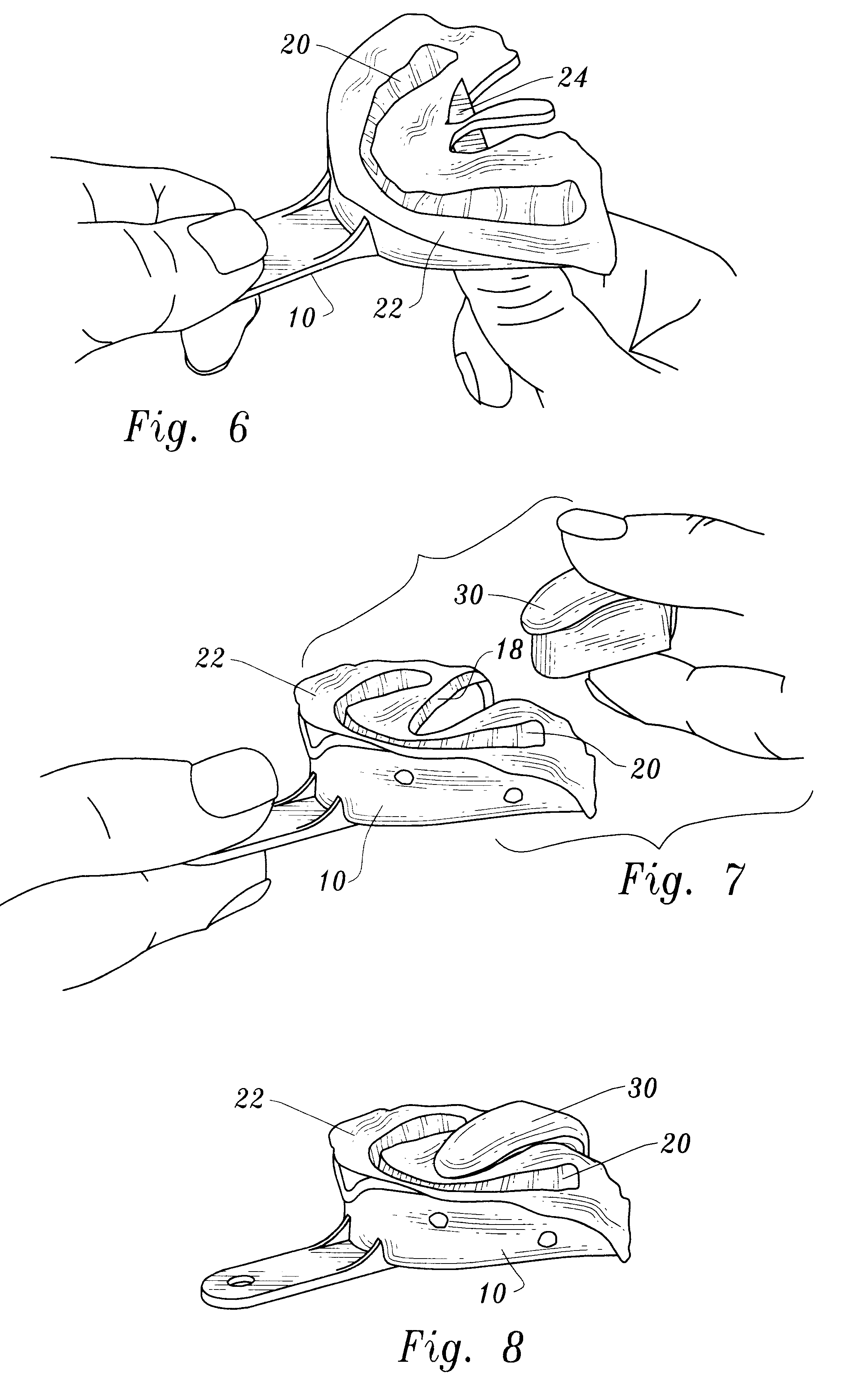
After the impression has been made by virtue of the dentist pressing the patient's teeth into the impression material, the tray and impression material are removed from the mouth. FIG. 6 illustrates the dental impression tray top side up and an impression 20 formed in the impression material 22. In FIG. 6 a knife...


PUM


Abstract

A block member is selectively positioned on a dental impression tray with an outer engagement surface of the block member in engagement with the tray portion defining a lingual recess to block entry of plaster or other casting material into the lingual recess.

Description

This invention relates to the dental arts, and more particularly to an apparatus and method employed when taking dental impressions and making casts of the impressions.Dental impression trays are widely used to take teeth impressions and form casts from the impressions. Dental impression trays form a concavity or interior in which soft impression material is placed. The impression tray and impression material are then introduced into a patient's mouth. An impression is made by the dentist positioning the impression tray and impression material over the patient's teeth and applying pressure so that the impression material disperses around the teeth and dental arch.The dental impression tray and impression material are removed from the patient's mouth after the impression is made. The next step in the process is to pour plaster or other casting material into the impression and into the interior of the dental impression tray.Lower dental impression trays typically define a lingual rece...

Claims


Application Information

Patent Timeline
Patent Type & Authority Patents(United States)
IPC IPC(8): A61C9/00
CPCA61C9/00A61C9/0006
Inventor MAYWEATHER, GEORGE S.
Owner MAYWEATHER GEORGE S
Why Eureka
Try Eureka