Vibrating screed and method of making same

a technology of vibrating beams and screeds, which is applied in the field of vibrating beams or screeds, can solve the problems of complicated mounting of such beams

Inactive Publication Date: 2001-11-27
B MAC MET
View PDF10 Cites 34 Cited by
  • Summary
  • Abstract
  • Description
  • Claims
  • Application Information

AI Technical Summary

Problems solved by technology

The known embodiments of such vibrating devices show the disadvantage that the mounting thereof is rather complicated and, consequently, time-consuming

Method used


Image

  • Vibrating screed and method of making same
  • Vibrating screed and method of making same
  • Vibrating screed and method of making same

Examples


Embodiment Construction

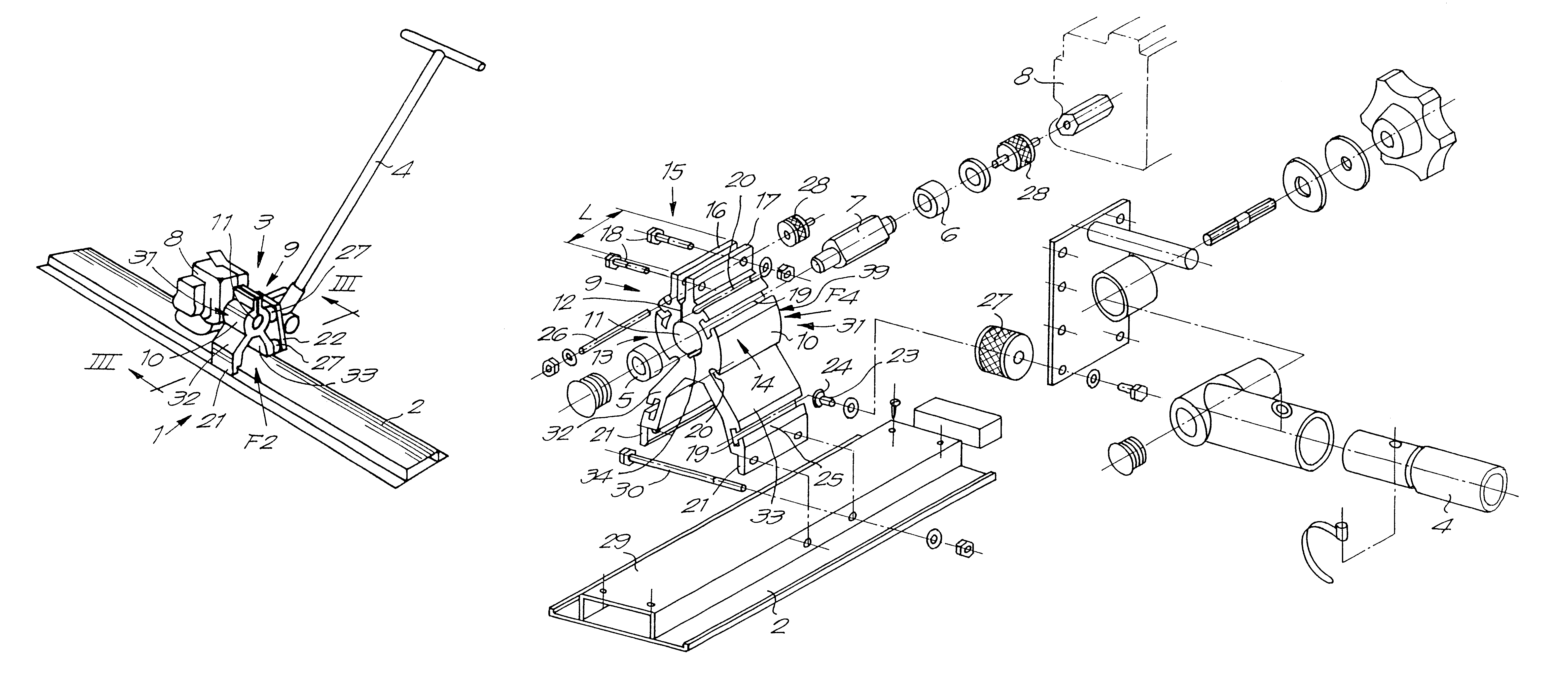
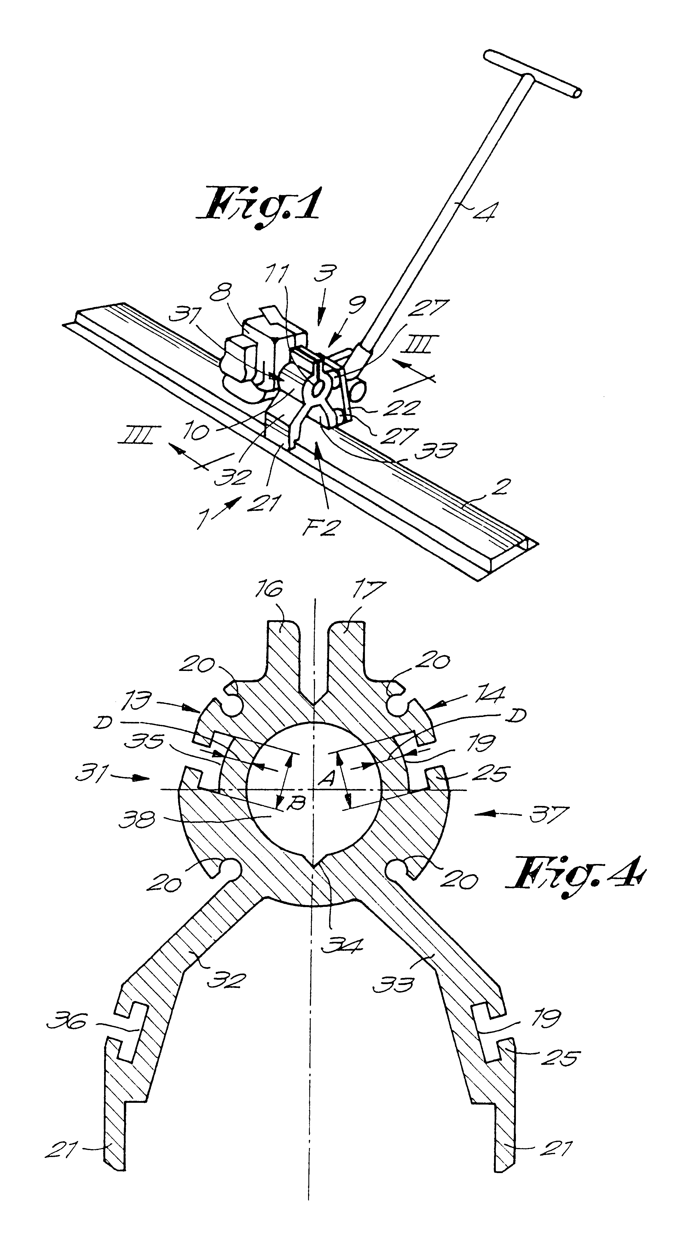
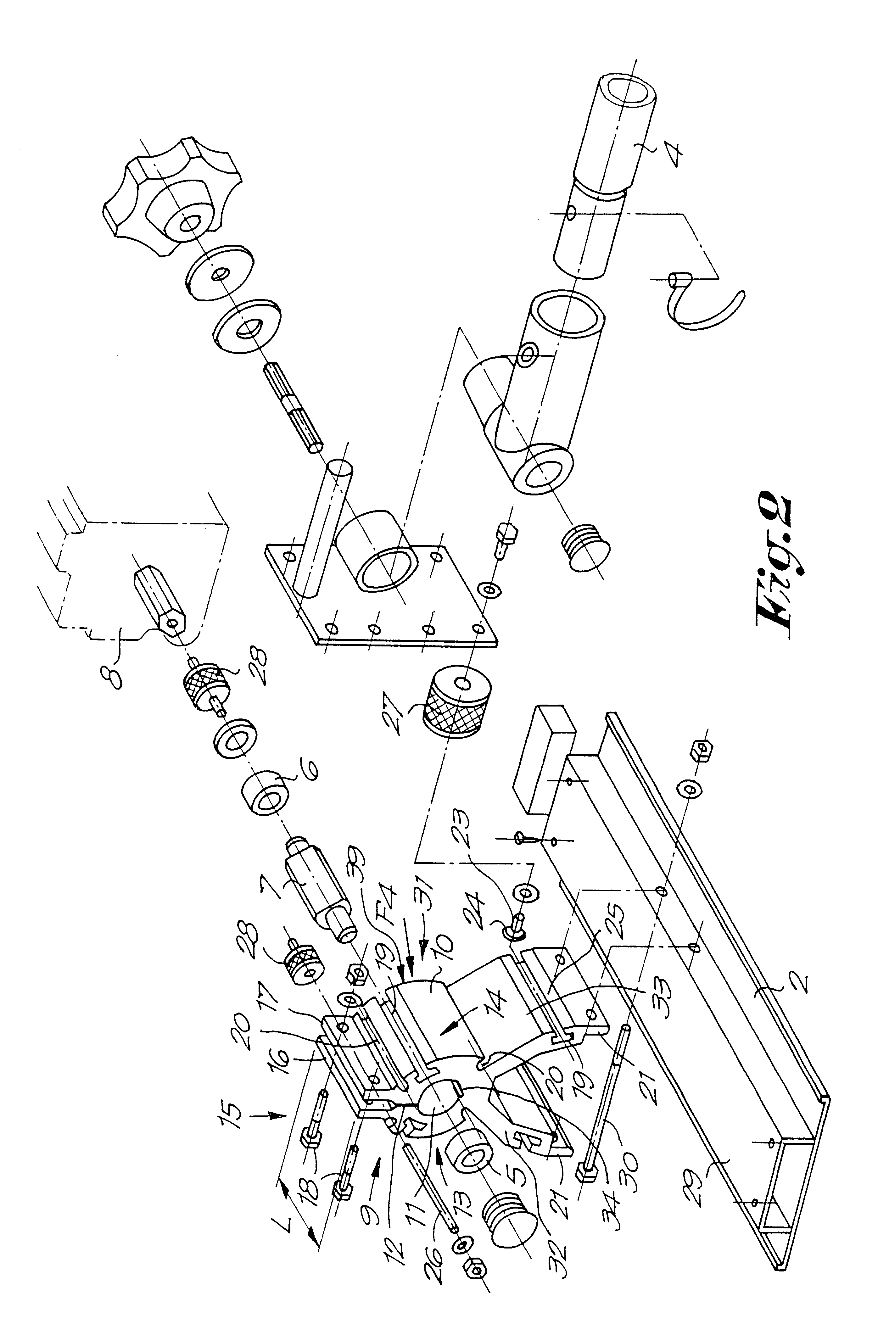
As represented in FIG. 1, the vibrating device 1 of the invention substantially consists of a vibrating board 2, a vibrating mechanism 3 cooperating with the vibrating board 2, and a handle 4. As represented in FIG. 2, the vibrating mechanism 3 substantially is formed by an eccentric 7 seated in bearings 5-6, and a motor 8 for driving the eccentric 7.

The particularity of the invention consists in that the bearings 5-6 and the eccentric 7 beared therein are fixed by means of a clamping mechanism 9.

The clamping mechanism 9 substantially consists of, on one hand, a body 10 in which a cavity or seat 11 for the bearings 5-6 is provided, whereby the body 10 is split apart at one side of the seat 11, more particularly, comprises a through recess 12, in such a manner that the body 10 shows at least two split body portions 13-14 which can be drawn towards each other, and, on the other hand, tensioning means 15 for drawing the aforementioned portions 13-14 towards each other and thereby clamp...


PUM

PropertyMeasurementUnit
sizeaaaaaaaaaa
circumferenceaaaaaaaaaa
bending flexibilityaaaaaaaaaa

Abstract

A vibrating screed for processing a floor layer, more particularly a so-called vibrating beam, of the type including a vibrating board (2), a vibrating mechanism (3) cooperating with the vibrating board, and a handle (4) whereby the vibrating mechanism comprises an eccentric (7) seated in bearings (5-6) and a motor (8) for driving the eccentric, wherein the bearings and the eccentric are fixed in a split body by means of a clamping mechanism on the split body.

Description

1. Field of the InventionThis invention relates a vibrating device for processing a floor layer, more particularly a so-called vibrating beam or screed, of the type substantially consisting of a vibrating board, a vibrating mechanism cooperating with the vibrating board, and a handle, whereby the vibrating mechanism substantially consists of an eccentric seated in bearings and a motor for driving the eccentric, and the bearings and the eccentric born therein are fixed by means of a clamping mechanism.2. Related ArtSuch vibrating devices are applied for spreading and smoothing of hardenable materials when forming a floor layer, more particularly materials such as concrete and similar.The known embodiments of such vibrating devices show the disadvantage that the mounting thereof is rather complicated and, consequently, time-consumingThis is for instance the case with the vibrating device disclosed in U.S. Pat. No. 5,244,305. This device comprises a rotating off-center weight borne in ...

Claims


Application Information

Patent Timeline
Patent Type & Authority Patents(United States)
IPC IPC(8): E01C19/22E04G21/10E01C19/40
CPCE01C19/402E04G21/10Y10T29/49792Y10T29/49696
Inventor RIJKERS, WILHELMUS CORNELIS HENRICUS MARIA
Owner B MAC MET
Why Eureka
Try Eureka