Safe needle device for syringe

a needle device and safe technology, applied in the field of safe needle devices for syringes, can solve the problems of scattered devices, inconvenient use, and inability to meet the needs of administering medical staff, and achieve the effects of inviting infection, avoiding infection, and avoiding infection

Inactive Publication Date: 2001-11-27
INT TECH GROUP
View PDF6 Cites 95 Cited by
  • Summary
  • Abstract
  • Description
  • Claims
  • Application Information

AI Technical Summary

Benefits of technology

It is a general object of this invention to provide an improved safe needle device for syringes.
In accordance with the above object, there is provided a needle-stick safety syringe comprising an inner tubular body, plunger, and extended needle at the distal end of the tubular body. A larger protective tubular body is concentric with the inner tubular body and freely slidable thereon. Spring means between the proximal ends of the tubular bodies bias them apart. Latch means oppose the biasing including a collar with a flexible cantilevered stop, such collar being permanently fixed to the distal end of the inner tubular body and having an outer diameter which freely slides within the protective tubular body. The stop hooks against a distal edge of the protective tubular body whereby the bias of the spring means is opposed. Slot means in the protective tubular body near its proximal end receive and capture the stop when pushed by a finger of a hand grasping said protective tubular body.
In addition, a method is provided of constructing a needle stick safety syringe having an inner tubular body terminating in a flange at its proximal end, a plunger, and extended needle at its distal end comprising the following steps. A larger concentric protective tubular body is provided which slides over the inner tubular body of the syringe. The proximal end of the larger tubular body is plugged serving as an abutment holding a coil spring against the flange. A collar is provided with a flexible cantilevered stop and an inner diameter capable of being permanently affixed to the distal end of the syringe body. The collar has an outer diameter which will freely slide in the protective tubular body. The coil spring is placed on the syringe tube, the plug and subsequently the protective tubular body is slid against the spring bias and the stop is affixed until the cantilevered stop hooks against a distal end of the protective tubular body, whereby pushing the stop allows it to ride against the inside of the protective tubular body which then covers the exposed needle due to the expansion of the coil spring. A slot is provided in the proximal end of the protective tubular body in which the stop is captured thereby limiting expansion of said spring and movement of the protective tube under the bias of the expanding coil spring.

Problems solved by technology

With the advent of AIDS and other highly infectious diseases, syringes and scalpels and other sharp devices have caused numerous injuries and infections to the administering medical staff.
Protective devices have been proposed, but these devices have been scattered and non-functional and are not user-friendly.
In addition, the maneuvering to accomplish the foregoing may cause an inadvertent puncturing of the nurse's own skin, thus inviting infection.
One such device requiring a two-handed operation is Badger U.S. Pat. No. 5,885,257, which is a very cumbersome releasable retaining device to retract the needle syringe where it will not cause harm.

Method used


Image

  • Safe needle device for syringe
  • Safe needle device for syringe
  • Safe needle device for syringe

Examples


Embodiment Construction

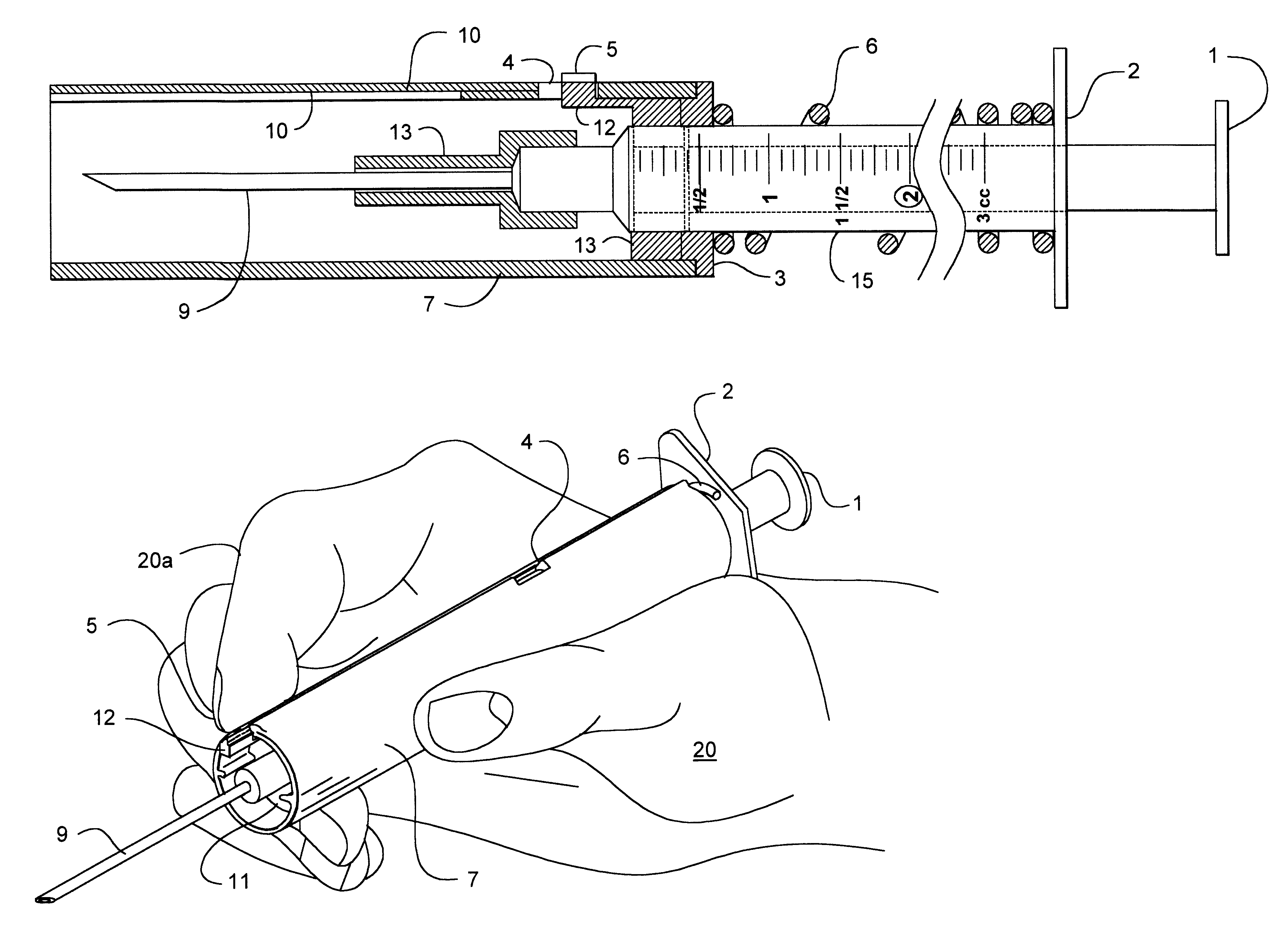
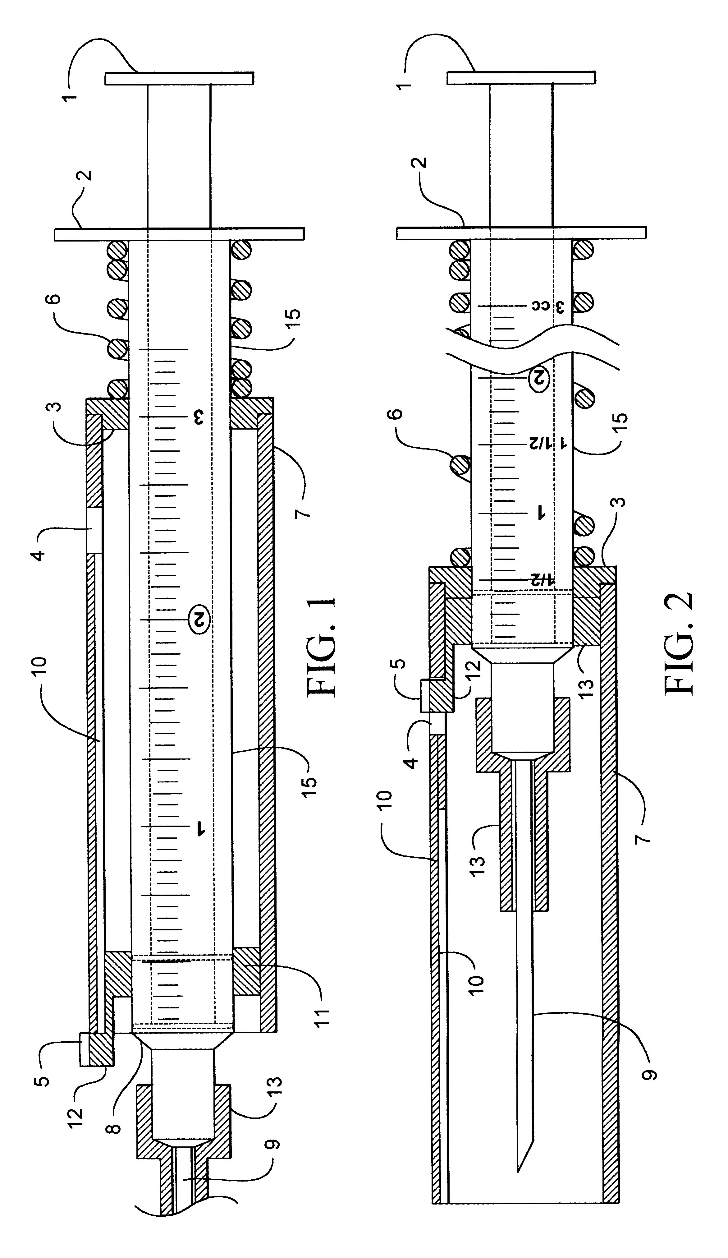
Referring now to FIG. 1, a typical commercial syringe of the so-called "TB" type, that is with a 3cc capacity and is illustrated with an inner tubular body 15, a plunger 1 that slides within the tubular body operates in the standard manner. The inner tubular body 15 has a flange 2 at its proximal end and an extended needle 9 at its distal end 8 with a protective cover 13.

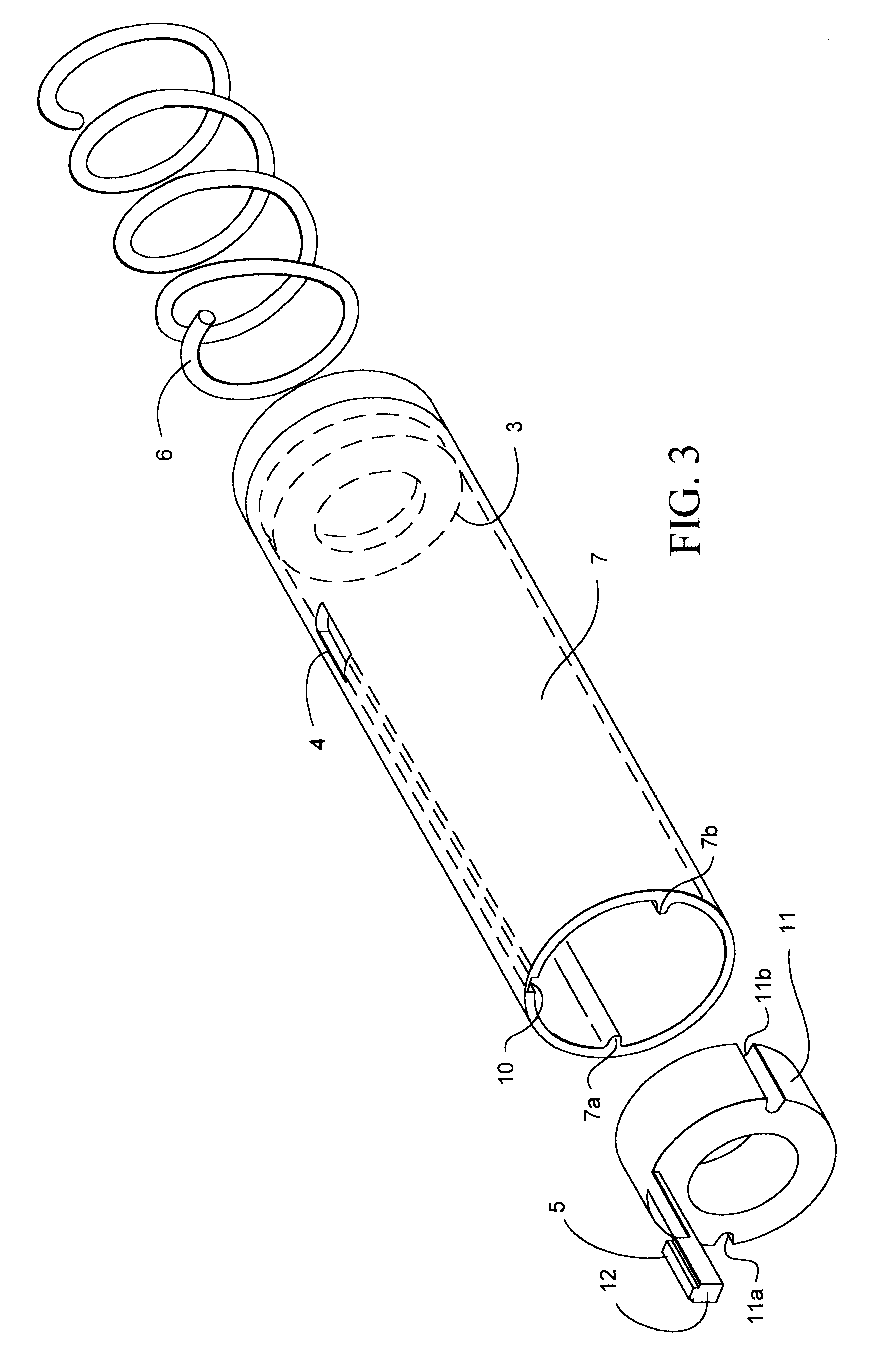
At that distal end 8 in accordance with the technique of the present invention, there is provided a collar 11 which is permanently or friction fitted or affixed onto tube 15 at the distal end and which carries a cantilevered stop 12 (which is flexible) having a button-type termination 5 which is easily engageable by a human hand 20 (see FIG. 4).

A larger concentric protective sleeve type tubular body 7 (having a diameter larger than the inner syringe body 15) is slidable over the syringe body as illustrated in FIG. 1, and includes at its distal end a plug 3. Syringe body 15 is freely slidable within that plug. A coil...


PUM

PropertyMeasurementUnit
outer diameteraaaaaaaaaa
flexibleaaaaaaaaaa
inner diameteraaaaaaaaaa

Abstract

A needle stick safety syringe includes a outer tubular protective cover or sleeve for the inner syringe body where a concentric coil spring is compressed against the normal flange of the inner syringe body and retained there by a stop which is cantilevered from a collar affixed to the distal end of the inner syringe body. This cantilevered stop also includes a convenient button which may be easily depressed by a finger of one hand holding the outer tubular body to allow the sleeve to be slid over the needle under the bias of the spring. The cantilevered button and stop rides in a groove in the inner diameter of the tubular outer protective body and is captured by a slot which effectively prevents reuse.

Description

INTRODUCTIONThe present invention is directed in general to a safe needle device for syringes as used in the medical industry and hospitals.BACKGROUND OF THE INVENTIONWith the advent of AIDS and other highly infectious diseases, syringes and scalpels and other sharp devices have caused numerous injuries and infections to the administering medical staff. Legislation has been enacted, including California (State of California Labor Code .sctn.144.7(d)) requiring some type of protection to the medical staff.Protective devices have been proposed, but these devices have been scattered and non-functional and are not user-friendly. For example, a nurse must use two hands to prepare a patient for an injection. One hand is used to clean the area to be injected with a disinfectant while the other hand is used to inject the needle into the tissue. After removing the needle from the patient, the administering nurse must press on to the spot of injection and hold the syringe in the other hand. A...

Claims


Application Information

Patent Timeline
Patent Type & Authority Patents(United States)
IPC IPC(8): A61M5/32A61M
CPCA61M5/3257Y10T29/53339A61M2005/3247
Inventor GRABIS, DIETRICH W.KAEHLER, MARY ANNEMELLBERG, KENNETH
Owner INT TECH GROUP
Why Eureka
Try Eureka