Arm support and pad for mouse using the same

Inactive Publication Date: 2001-12-11
CARL JIMUKI
View PDF9 Cites 9 Cited by
  • Summary
  • Abstract
  • Description
  • Claims
  • Application Information

AI Technical Summary

Benefits of technology

Next, in the sixth aspect of the present invention, since the pad body is provided with the hol

Problems solved by technology

Therefore, in case of using this displacing stand 3 for operation of the mouse this conventional displacing stand 3 can not rotate without changing the posit

Method used


Image

  • Arm support and pad for mouse using the same
  • Arm support and pad for mouse using the same
  • Arm support and pad for mouse using the same

Examples


Example

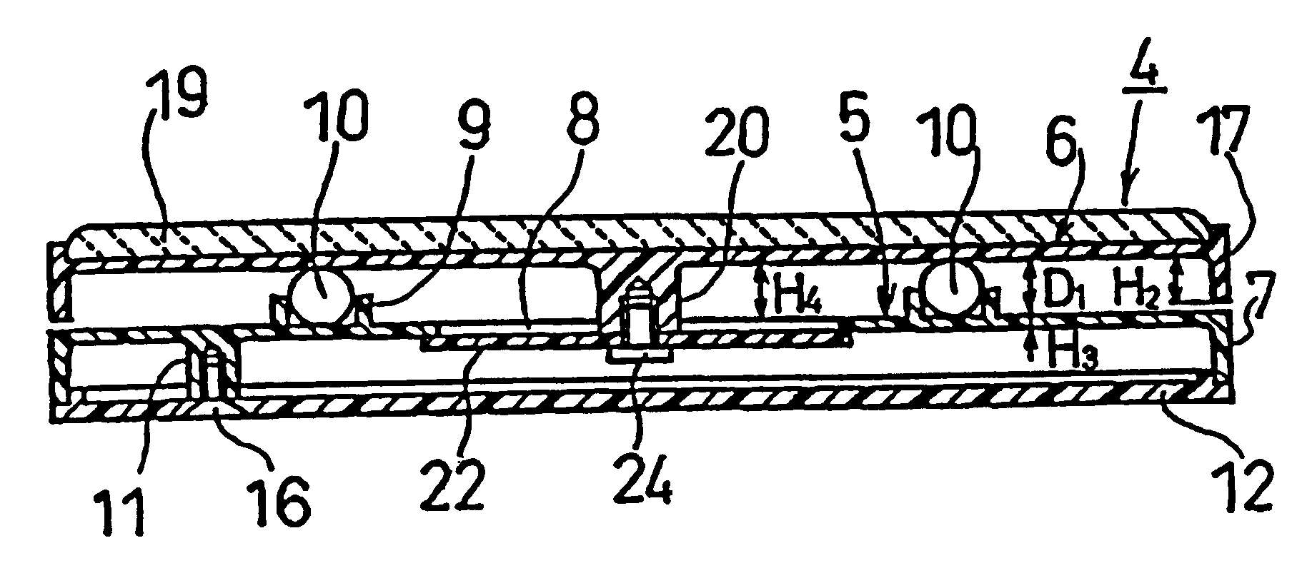
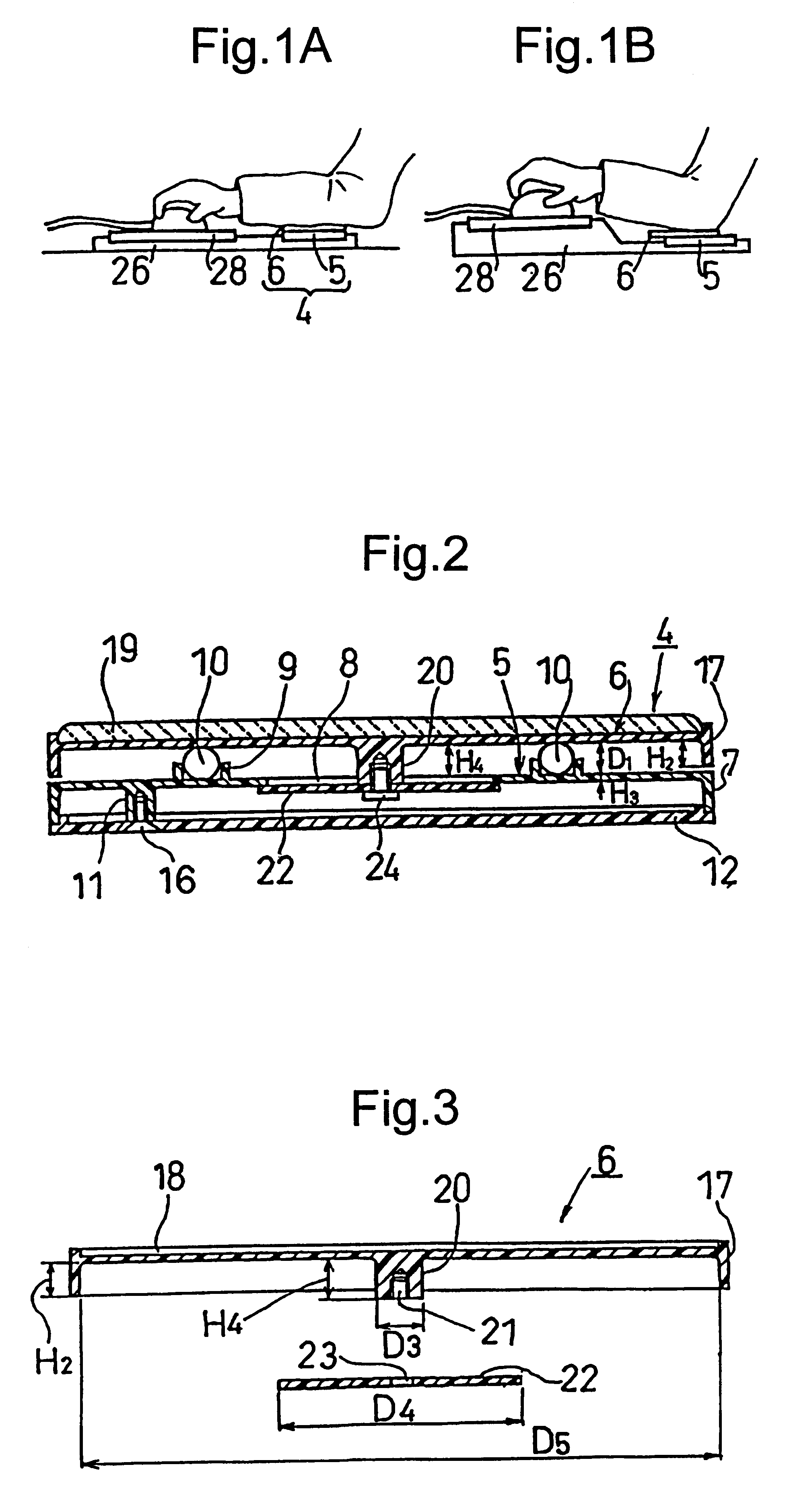
As shown in FIGS. 1(A) and (B), an arm support 4 is to support the arm to operate a mouse for a computer, which approximately is formed from a fixed stand 5 and a displacing stand 6.

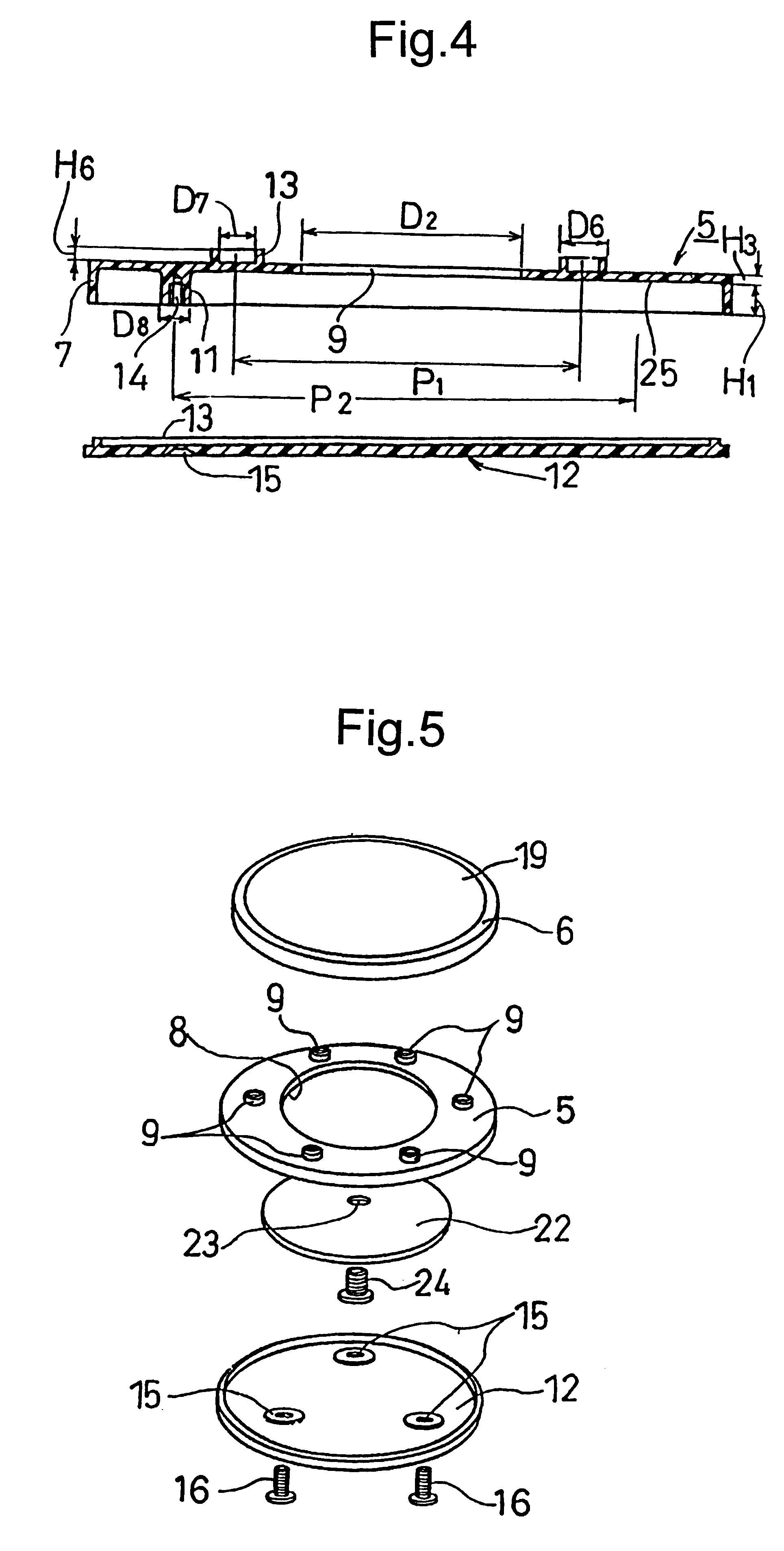
As shown in FIGS. 2, 4 and 5, a sectional configuration of the circular fixed stand 5 which forms the lower portion of the arm support 4 is in such a manner as a circumferential side edge 7 extends downward to make a height H1 and under the ceiling a spacing where later mentioned a back plate 22 can be displaced is provided. At the center portion of the fixed stand 5, an opening 8 is provided, around the opening 8 a plurality of ball receptors 9 are disposed annularly (pitch circle diameter P1) and the balls 10 are accommodated.

As shown in FIG. 4, from the ceiling of the fixed stand 5, a plurality of bosses 11 having the height H1 same to the side edge 7 are projected and annularly (pitch circle diameter P2) disposed. The lower ends of the side edge 7 and the bosses 11 abut to the bottom plate 12, on the...


PUM


Abstract

An arm support 4 which is formed by placing the displacing stand 6 provided with the boss portion on the fixed stand 5 on the surface of which is formed with a hole and the pad body 28 are coupled with the recessed portions formed on the pad stand 26. Thereby, the displacing stand 6 is enabled to displace in parallel and rotate on the fixed stand 5, which causes to be miniaturized in its total size. Further, when operating a mouse by placing an arm on the arm support 4, since the arm does not rub the table on which the pad stand is placed and the wrist including shoulder move in association with each other, resulting in reducing the fatigue of arm and increasing the working efficiency.

Description

1. Field of the InventionThe present invention relates to an arm support stand and a pad for a mouse using such the arm support. In general, when operating something on a table or desk, for instance whendepicting a linear line using a scale, operating a keyboard of such as personal computer or operating a mouse for personnel computer, it is often carried out by floating an elbow from the desk, and since, in such a case, the arm is easily to be fatigued, the elbow is apt to be put on the desk, so that movement of the arm becomes awkward.The present invention relates to an arm support for helping of the above arm operation and a pad for a mouse using the same.2. Prior ArtAs an example when operating something on the desk by hand, in particular, when operating a mouse for a personal computer, it has been adapted to be carried out by putting a sponge or gum pad on the desk and while resting an arm or floating the arm on the desk. Further, it has been known that, in place of putting an e...

Claims


Application Information

Patent Timeline
IPC IPC(8): A47B21/00A47B21/03G06F3/033G06F3/0354G06F3/039
CPCA47B21/0371G06F3/03543G06F3/0395A47B2200/0085
Inventor MORI, MAKOTO
Owner CARL JIMUKI
Why Eureka
Try Eureka